Keyboards and gamepads and ports, oh my!
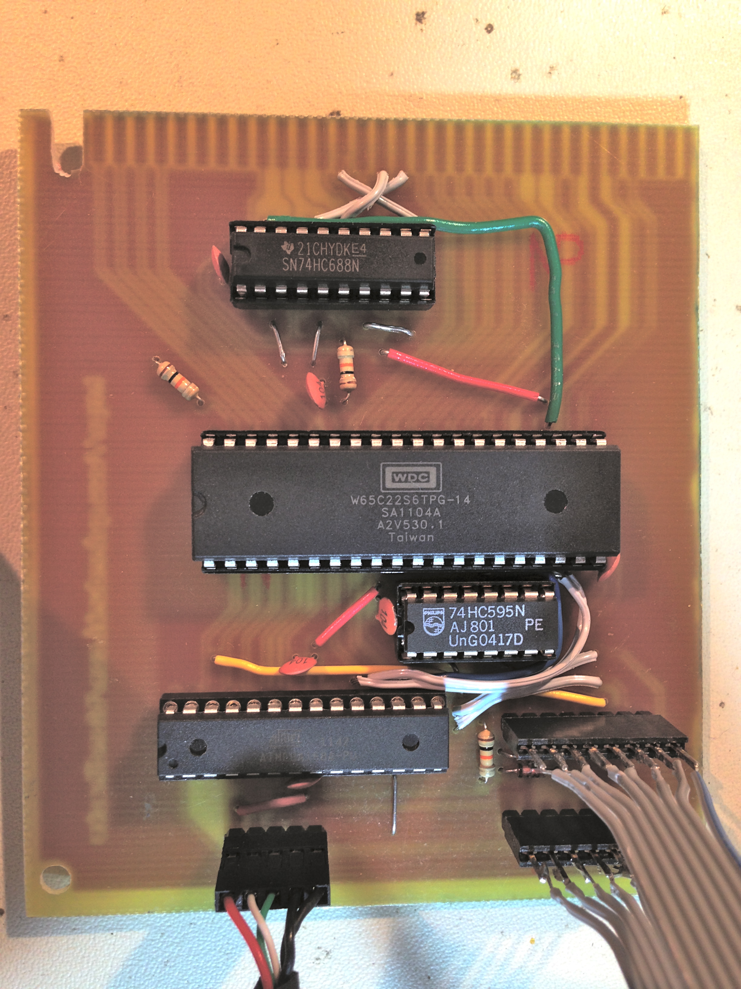
With Veronica’s input systems working in prototype form, it’s time to get it all installed in the case. The first step in that process is to build a PCB for the keyboard/gamepad circuit, which I’m calling the Input Board. It’s a stunningly inspired bit of nomenclature, I know. Mr. Pulitzer, please email me for where to send the award.
I’ll spare you the gory details of building the board, since I’ve documented that ad nauseum already on this project.
After etching this board, I immediately spotted a face-palm-worthy problem.
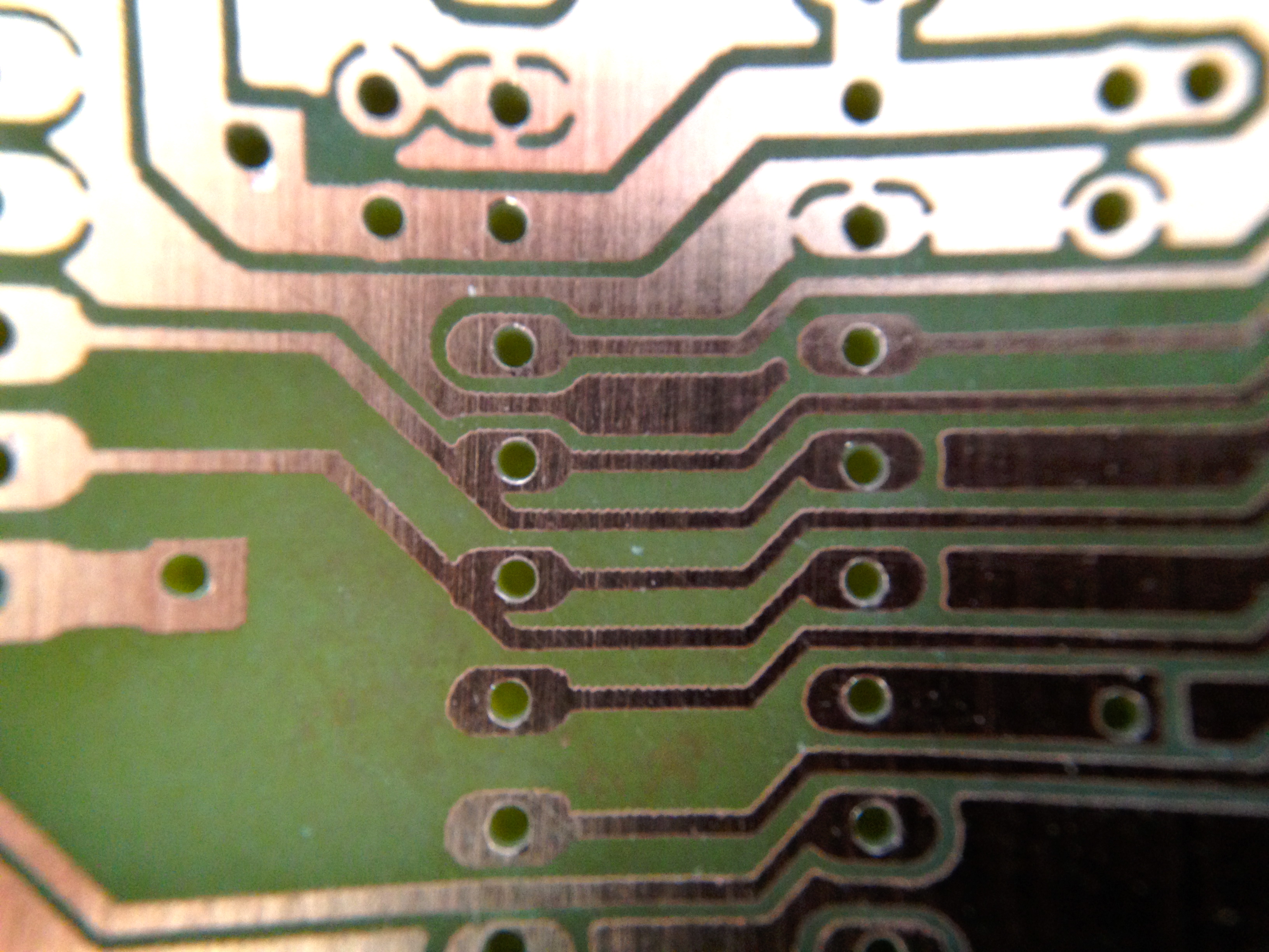
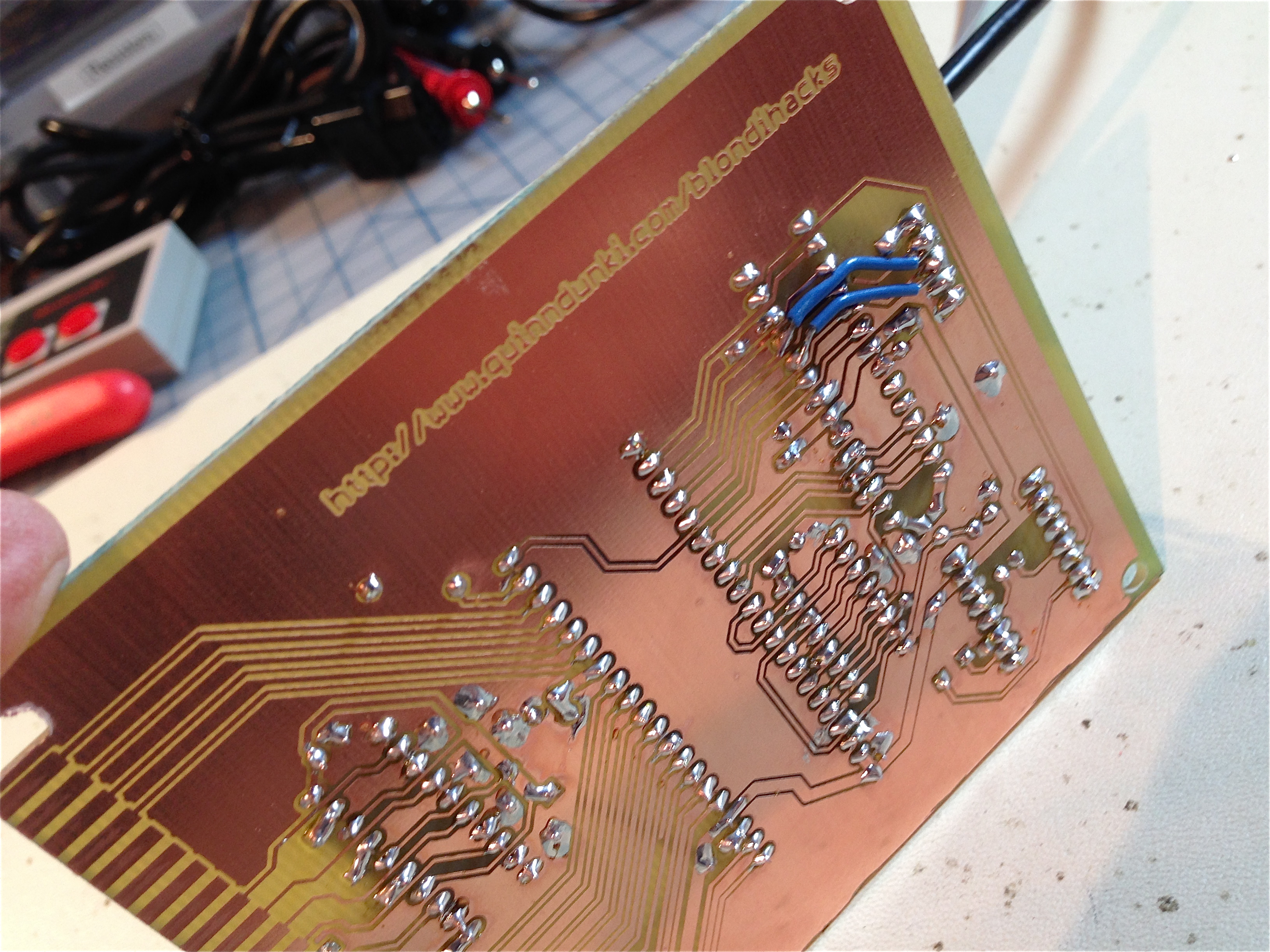
Luckily, that was easy to spot. I broke the traces with a sharp knife, and ran jumpers in their place. It looks like I did a Group Move in Eagle on that chip, and didn’t successfully select all the relevant trace nodes. The ERC and DRC checks in Eagle both would have caught this, but as you can guess, I didn’t run them this time. Whoops!
That fixed, I started testing the board under power. My initial tests turned up one tiny niggling problem. When the board was plugged in, Veronica wouldn’t boot. At all. Somehow the presence of this board broke the whole computer. That’s a pretty odd problem, to say the least. There were no dead shorts or anything, but the boot ROM code simply refused to execute. With a mysterious problem like this, my first step is to start pulling chips off the new board to see if the problem goes away. It’s a primitive debugging method, but a quick way to eliminate variables. Well, I ended up pulling every single chip off the board, and the problem persisted. If the bare PCB was on Veronica’s backplane, the ROM wouldn’t boot. Clearly there had to be an error on the board itself.
A visual inspection of the board didn’t reveal any issues. The only clue I had was that Veronica’s power consumption went up about 150mA with the new board plugged in. There isn’t enough hardware on the new board to account for that, but the increase is too small for a dead short. Furthermore, the increase in current persisted even with all the chips removed from the new board. The evidence was pointing to a weak short of some kind, so I started testing all the signal traces for continuity to the ground plane. Sure enough, here’s what I found:
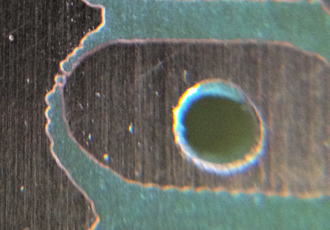
The pad shown is an address line. So, the ROM wasn’t booting because an address line on the bus was being held low, foiling all attempts to decode addresses or fetch code from memory. No wonder it wouldn’t boot! The error is a result of me pushing my etching clearances a little bit too far, as I detailed in a previous post.
With the board complete, I needed to install ports to plug in the peripherals.
I decided to repurpose the knob mounting holes. I needed two gamepad ports and a keyboard port, and the sizes were already pretty close to what I needed. It also saves me measuring to get things spaced out nicely. Thanks, Philco!
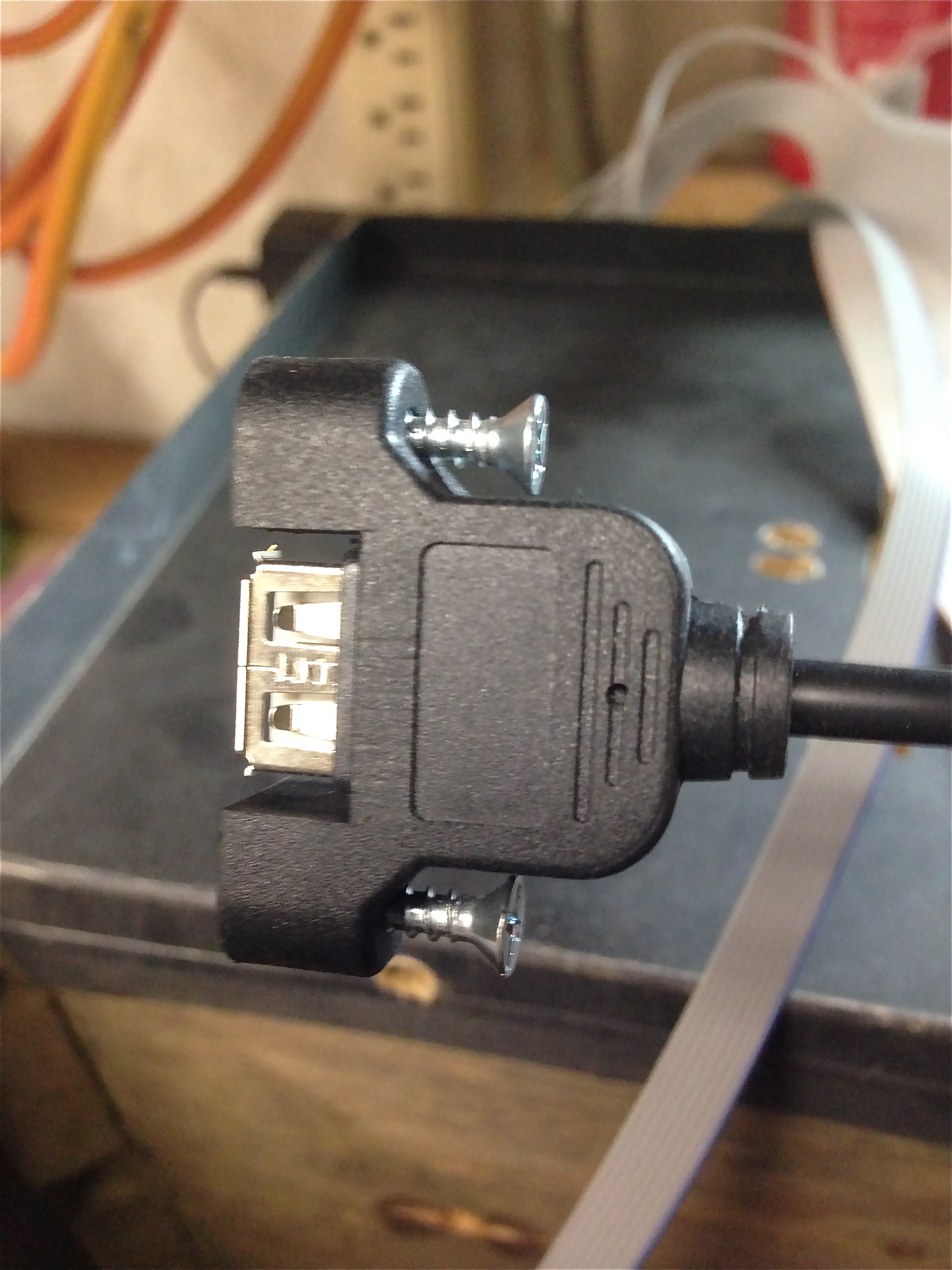
The keyboard goes in the middle. The hole was already very close to fitting a USB plug. I just needed to square out the middle with a sharp chisel.

The connector is designed to be mounted in a sheet-metal PC case, so it has some captive nuts in the plastic housing, and it came with small machine screws. These weren’t long enough to go through Veronica’s much classier wood casing. Besides, I didn’t want screw heads showing on the front. Instead, I just drilled out the captive nuts, and ran wood screws through the plastic from behind.
The D-Cannon connectors for the NES gamepads were a little tricker. They have no obvious method of mounting them at all. There are little tabs on the sides, so perhaps those were held captive in some sort of plastic moulded bracket on the original NES case. That wasn’t going to work here.
Instead, I opted to break off those tabs, and simply press-fit the connectors into the wood case. The wood is thick, so there’s lot of friction area to hold them. If they work loose, I can always add some glue later. So far though, they are holding very well.
To get a precise press-fit, I traced the outline of the connectors around the hole.
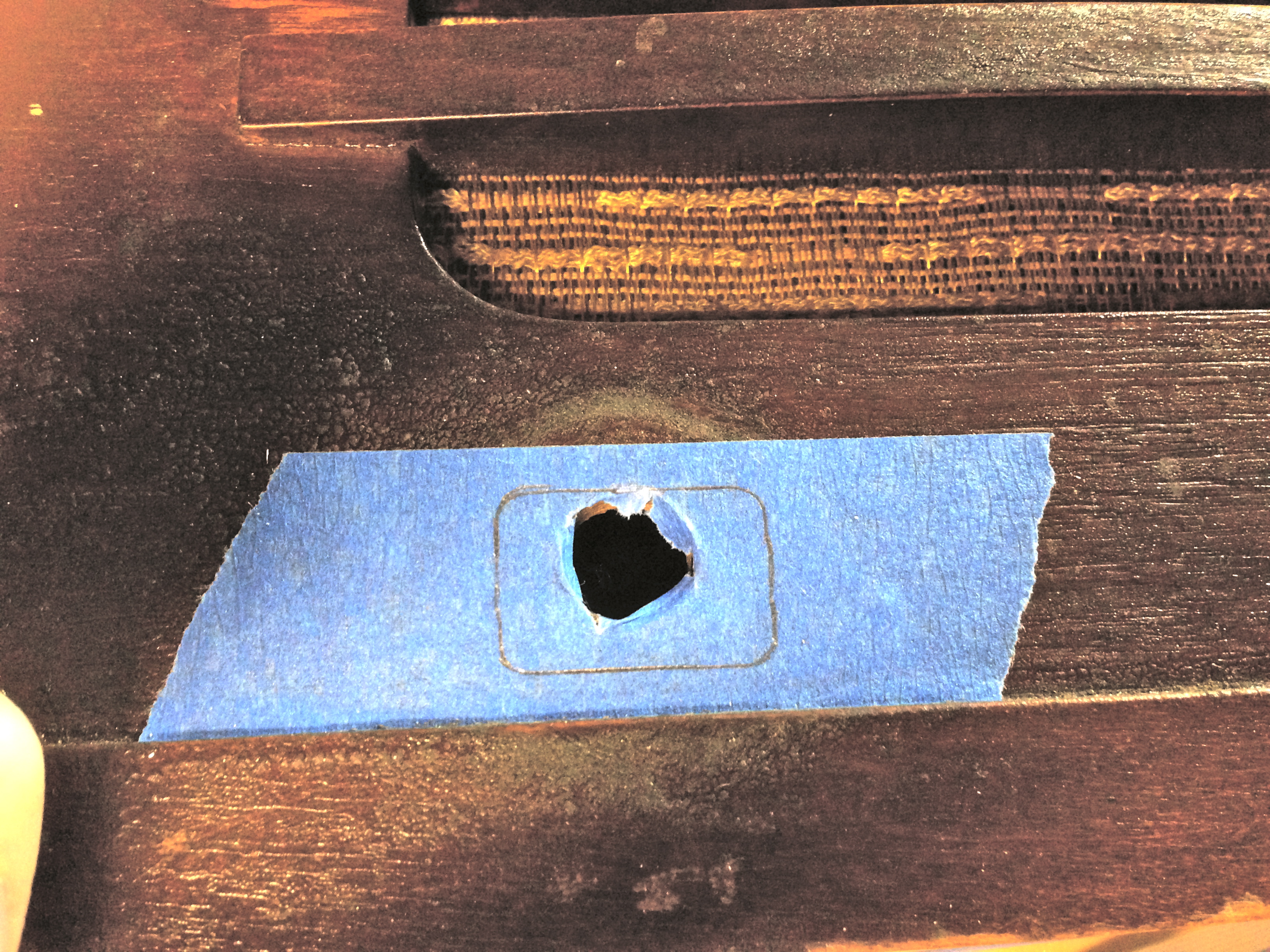
Note that the corners of the hole need to be rounded. I chose a drill bit that has the same radius as those rounded corners, and drilled them out very carefully. Then, I used a sharp chisel to “connect the dots” as it were. If you take your time, and your chisel is sharp, this is easier to get right than it sounds. If in doubt, make the hole a hair too small, then test fit and file as needed until the connector is a tight fit.
Then it was just a matter of tapping the connectors into place with a block of wood and a hammer.
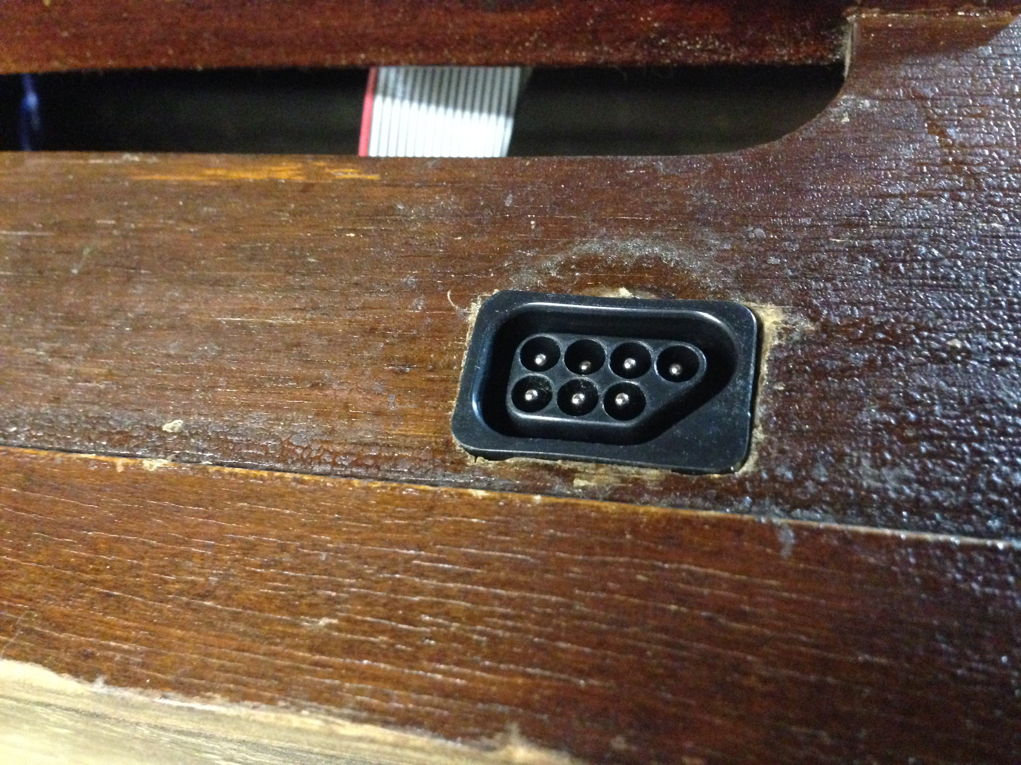
Repeat that process for the other side, and that’s all there is to it!
So, software next, I suppose? We shall see.
Looks like you had a fun holiday break! I was away from the workshop, so I didn’t get anything done. 🙁
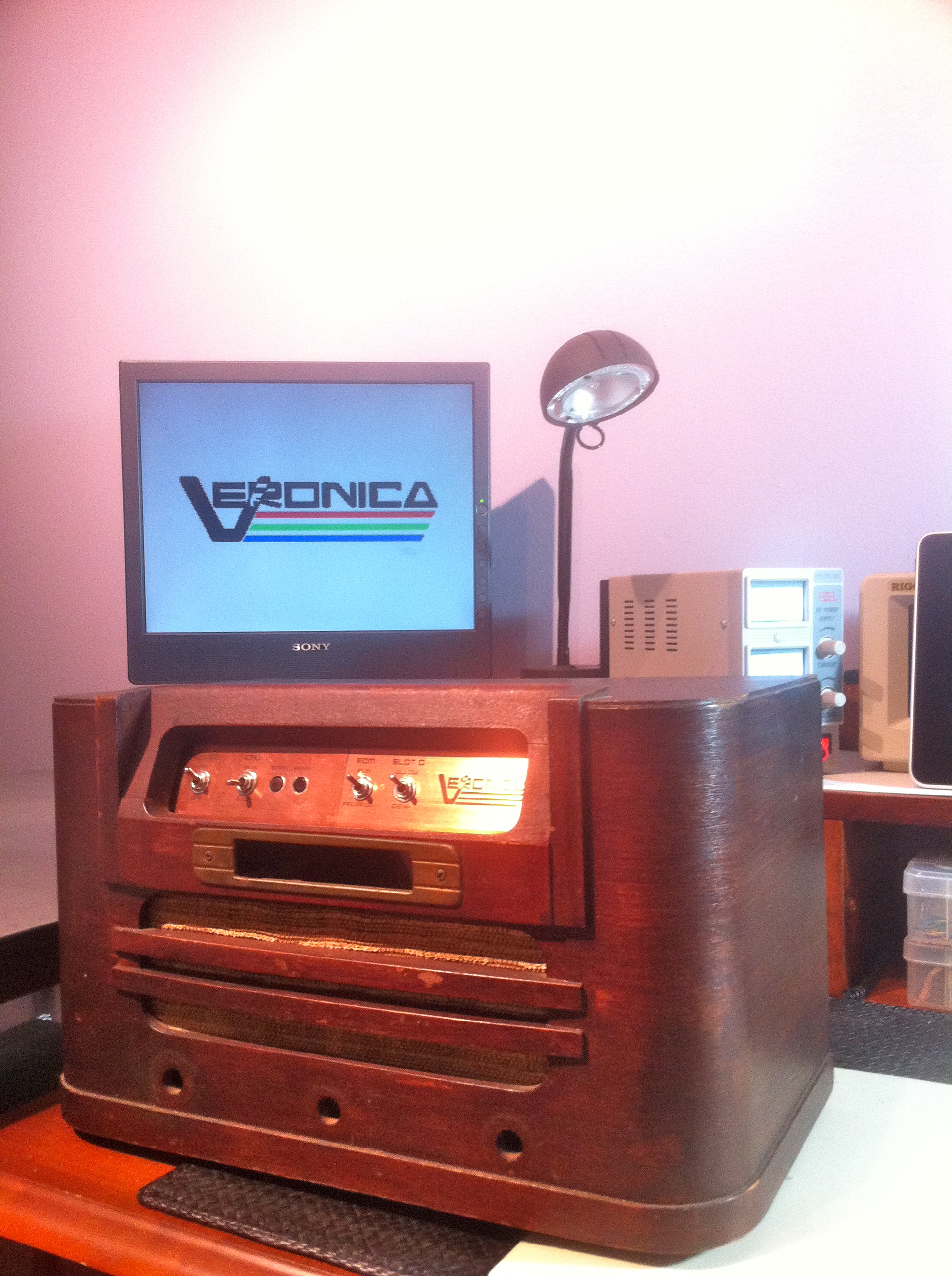
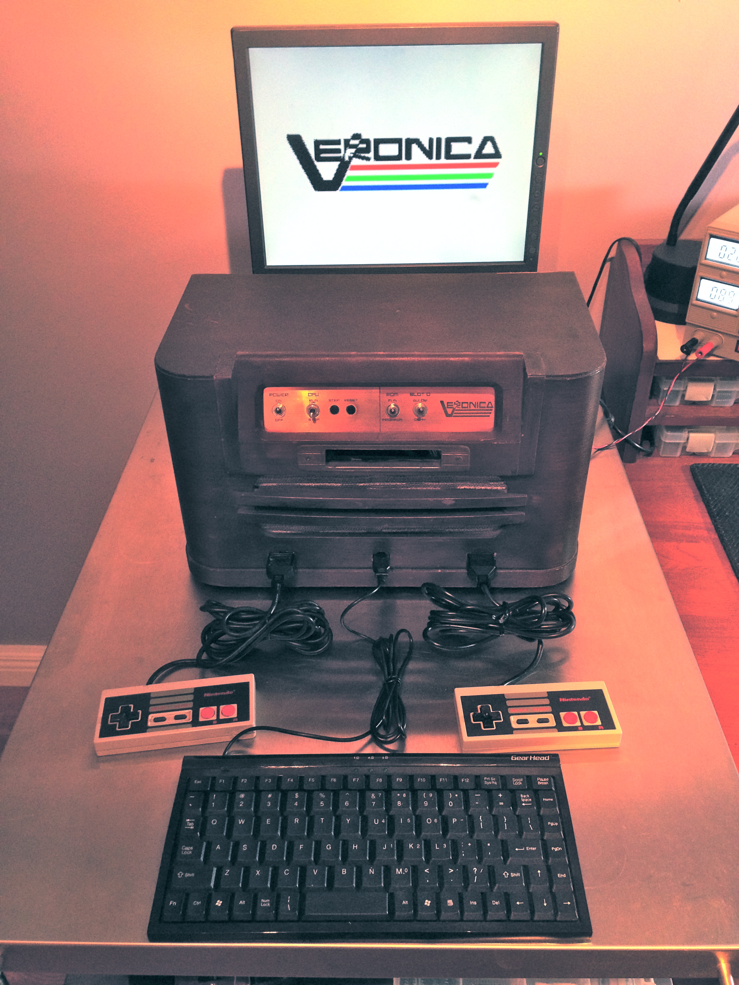
She’s looking great with stuff plugged in. Do you have any ideas to do something for a screen that matches?
Is Veronica far enough along now that you could actually write and run “real” programs?
Nice find on that bridge. It is tremendously fun to read about this project.
I am hoping to see Lunar Lander at some point 😀
Will it have a cartridge port? I’ll have to go back and look. Thinking it would be fun to make an SP0256 based TTS cartridge, n’est pas?
Maybe an SD card reader?
Actually, I don’t remember seeing an Audio I/O for Veronica. Is that on the cards? (Pun 100% intended.)
There isn’t currently audio, nope. Might be something that happens!
Hello Blondihacks!
Nice to see more progress. I really like how everything’s coming out well.
Have you considered to give Veronica a new friend *cough* SID *cough*? There’s plenty of songs available for it and it’s designed to work with the 6502. I think Veronica and Sid would have a good time together 🙂
Best wishes.
I have given some though to sound, and honestly I probably would not go for a SID chip, mainly due to cost. Unless you can find a C64 with the chip still on the board, the market is too hot. The chips themselves for $30-$40 on eBay. That’s more money than all the rest of Veronica’s chips combined. People buy up C64s by the truckload, just to strip the SIDs off them and sell them to retro synthesizer builders and such. It’s kind of a shame, really.
I would probably go for a Pokey chip (Atari’s sound chip from the same era). The Pokey is not quite as capable as SID, but it’s in greater supply, and the demand is much lower. You can get them pretty inexpensively from arcade suppliers, because a large number of arcade games used them.
It’s a bit of a crazy idea, but from a quick google, it looks like people have created SID chips on FPGAs. 🙂
I’ve never worked with an FPGA, I don’t know if you have, but I’ve always kind of thought it would be a fun learning experience, if only I could think up a project that interests me where an FPGA is the right way to go about it.
Interesting! If I understand the SID correctly, that would likely be more of a SID emulator. One of the tricky things about it is there were analog elements on the die. Each SID was a little bit different as a result, and any strictly digital implementation would have to fake that somehow. I could be wrong about this, though. I’m no expert on the SID.
As for FPGAs, I do intend to get to those at some point. The obvious Veronica application would be the video board. What I learned by bit banging it on an AVR is that bit banging it on an AVR is absolutely the wrong way to make a video board. 🙂 It’s BARELY possible to do it at all, and the end result is something that is functional but not very powerful or useful. Veronica has very harsh limits on the amount of pixels per frame that can be modified, for example.
What you’ve already said makes it obvious to me that you know way more than me about SID chips. 😉 I had no idea they incorporated analog elements that imbued them with a bit of uniqueness from chip to chip. It does make me wonder how the VHDL SID implementations my googling found dealt with it. One made some mention of not implementing filters… maybe that’s because the analog bits are in the filters?
FPGA video board seem like the way to go. I wonder if there are VHDL implementations of any old-school video chips out there that you could use as a starting point. Do you think you’d go that route, or try to create your own completely custom one from scratch?
The nice thing is you can just unplug the AVR-based video board and plug a new one! (And do some software.) Bus architecture FTW.
Is there a modern video chip that can output VGA and is simple, abundant and mainstream like the 6845’s of yore?
Before diving into make my own video “chip”, I did a ton of searching, trying to find something. I figured there must be some sort of low-end one-chip solution for bitmapped video. I never found anything. There some good candidates among surviving vintage chips, though. The Yamaha V9990 family of chips, for example, would be a great choice. They do show up on eBay, and can be found in some old MSX computers. It doesn’t output VGA exactly, but has an RGB signal which you could build an output circuit off of. It solves other side of the problem, managing video memory, color palettes, sprites, scan line interrupts, etc. I didn’t find out about the Yamaha chips until after I basically had my video board working, otherwise I would have given them serious thought.
There are a lot of impressive FPGA video implementations out there, both custom and copies of existing chips (such as Nintendo’s excellent PPU). I would probably learn from those, rather than writing something from scratch.
What about an OPL4? I believe they are still in production:
http://en.wikipedia.org/wiki/Yamaha_YMF278