A problem waiting to happen is no longer waiting.
I recently cleaned up and relocated the battery box on Johnny, because some previous owner had let it go to hell, and leaked alkaline all over the place. You may also recall that I waxed poetic about how Johnny had dodged a bullet, and how smart I was for catching this problem ahead of time, before any damage was done. I think you see where this is going.
That day is today.
It’s interesting how sometimes trying to do the right thing can “create” a problem. To be fair, I didn’t really create this problem, I just accelerated its appearance. That connector sat there for years with corrosion sitting all over it, working just fine. However, I disturbed things with my battery box modification, and set off this time bomb a little sooner than it would have otherwise gone off. That’s really a good thing, though. That bomb would have gone off either way. Might as well be now!
I’m getting ahead of myself here, though. Let’s rewind to how this all started. I was starting a new game, hoping to break my high score, when this started to happen:
That alarm (and associated message) is the high voltage interlock. The game thinks that the coin door is open, and is disabling the high voltage circuits in response. This is done as a safety measure, so you (theoretically) can’t electrocute yourself by opening the coin door and sticking your arm in there. The reality is, it’s probably still possible to do so, but it’s a nice safety feature that probably reduces the chances. Unfortunately, when this safety malfunctions, the game can’t be played. No high voltage means no flippers, no jet bumpers, no ball launch, no cyberglove, no flash lamps… well, no pinball really. It’s all about the high voltage!
The problem was intermittent. It would be fine for a few minutes, then go crazy, then be fine again. As any experienced software engineer can tell you, the first step in debugging an intermittent problem is to find a way to reproduce it. Debugging is a scientific process of controlling for variables, and you can’t do that if the results of testing a hypothesis are untrustworthy. Each attempt at a repair is an experiment to see if you found the right variable that was affecting the system.
In this case, the problem could be reproduced by simply leaving the machine in attract mode for a while. The problem would always occur within five minutes. That’s good- it gives us an outer bounds to test against. For insurance, we’ll double that. Any fix needs to last ten minutes to be sure the problem is cured.
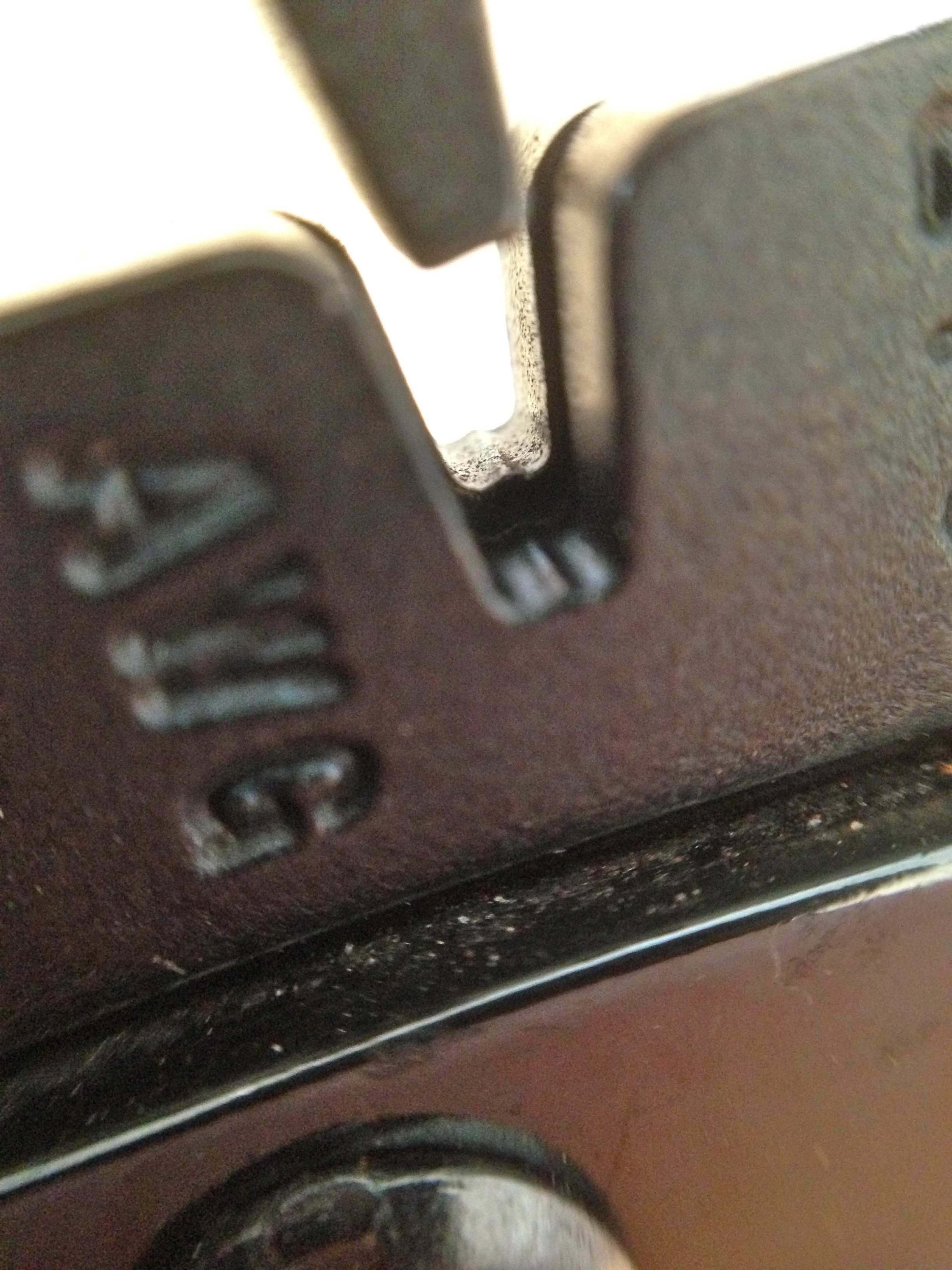
Okay, let’s get our hands dirty. Debugging always starts with the end-effector in the system. That’s where the least variables are. You then work your way back up the chain from there. In this case, the end-effector is the interlock switch on the coin door.
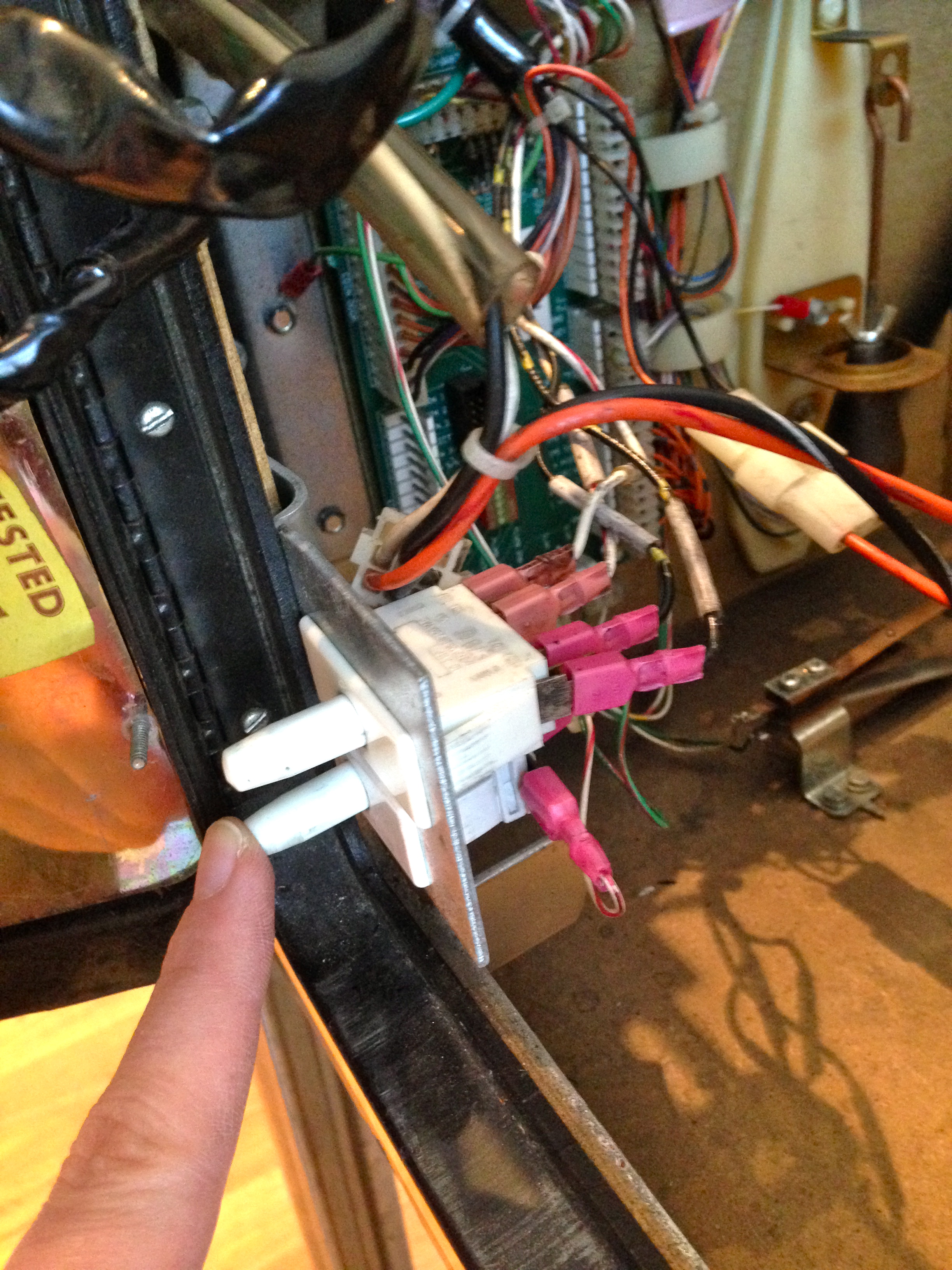
If those look like the door switches that control the light in your fridge, it’s because they are. The very same part. This is nice, because it’s a reliable switch, rated for a great many cycles. It’s also rated for 250V, but it’s only used for a 5V TTL logic signal here. Seriously overkill, but that’s commercial equipment for ya- built to take abuse.
The obvious first test was the physical switch itself. The ohmmeter showed perfect continuity with no intermittent behaviour. So much for the easy answer. Just in case, I shorted the switch with a jumper and ran my attract mode test. No dice. This problem isn’t the switch’s fault.
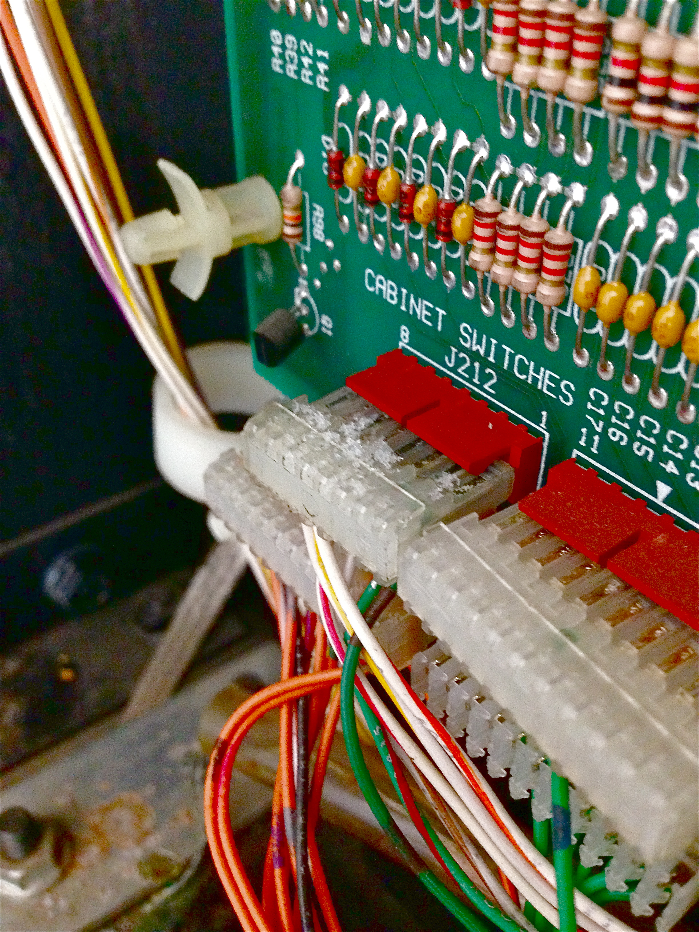
It’s time to meet the Coin Door Interface Board. Pinball machines have far too many switches to have a dedicated logic line for each one. They solve this problem the same way a computer keyboard does- by putting the switches into a matrix that is governed by diodes. The rows and columns of this matrix can be scanned by the CPU to check the status of each switch at regular intervals. All the buttons on the front of the cabinet (Start, Launch Ball, coin insertion, etc) are part of this matrix. This includes the high voltage interlock. All these switches go to the Coin Door Interface board, which acts as small remote extension of the CPU’s switch matrix. This way, only a small harness needs to be run back to the CPU board (instead of dozens of wires, as would be needed if every switch was wired all the way back to the main CPU matrix).
So, the next link in the chain is the harness connecting our switch to the Coin Door Interface Board. It was a simple matter to jumper past this harness to take it out of the loop.
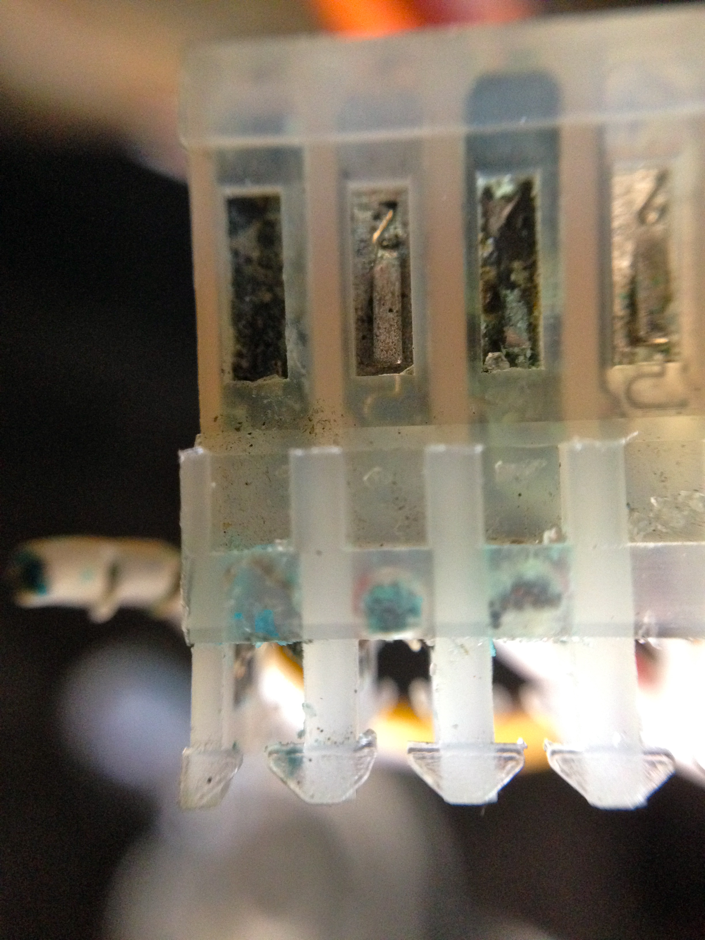
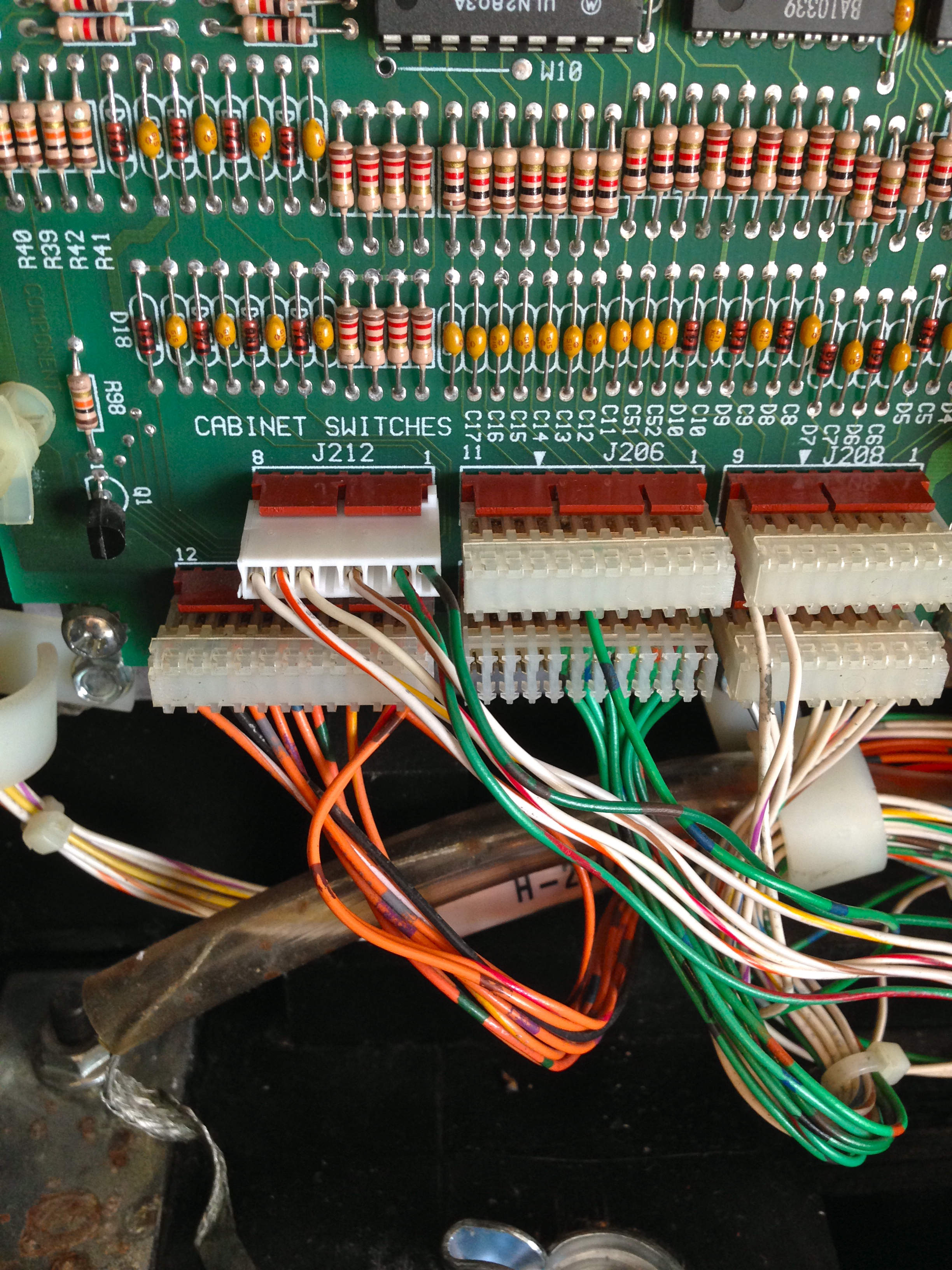
Interesting aside- note the size of the connectors (the two large ones in the above photo, one empty) for the coin mechanism. Designing a system that can take all denominations of coins in hundreds of different countries, and be configured to cost as much as the operator wants is not easy. Fully half of the large configuration system in the software is dedicated to building custom charts of cost structures for charging players to play in various different ways. Some engineer was tasked with designing this important system, and it was probably a thankless job.
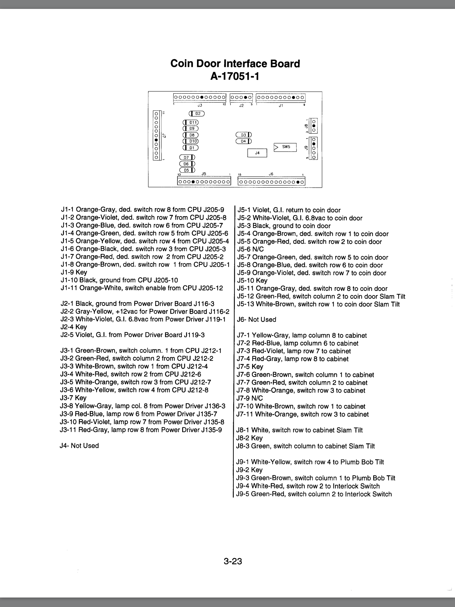
In any case, no problem with our first harness. The next potential weak link in the chain is the diode. Each switch in a switch matrix needs a diode in series with it. These diodes prevent cross-talk between switches on the same row and column, and it’s what allows the CPU to read one switch at a time, even though they’re all connected to each other. These diodes can weaken over time, and start to leak current. This leakage can cause intermittent switch problems like we’re seeing here.
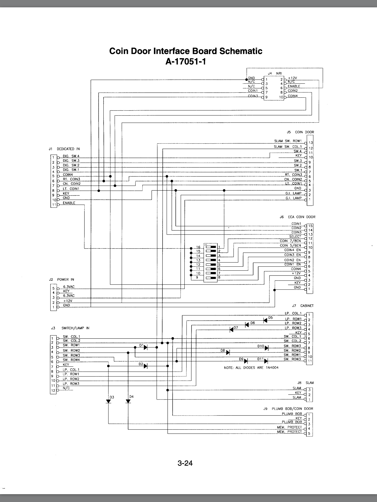
A quick probe on all the diodes connected to our switch circuit (using the diode test function on the multimeter) showed no problems. Another way to double check the diodes is to test the operation of other switches on the same row and column. The manual has a diagram of the entire matrix. I tested a couple of switches in the same row, and a couple in the same column as our troublesome interlock. All the diodes are working fine.
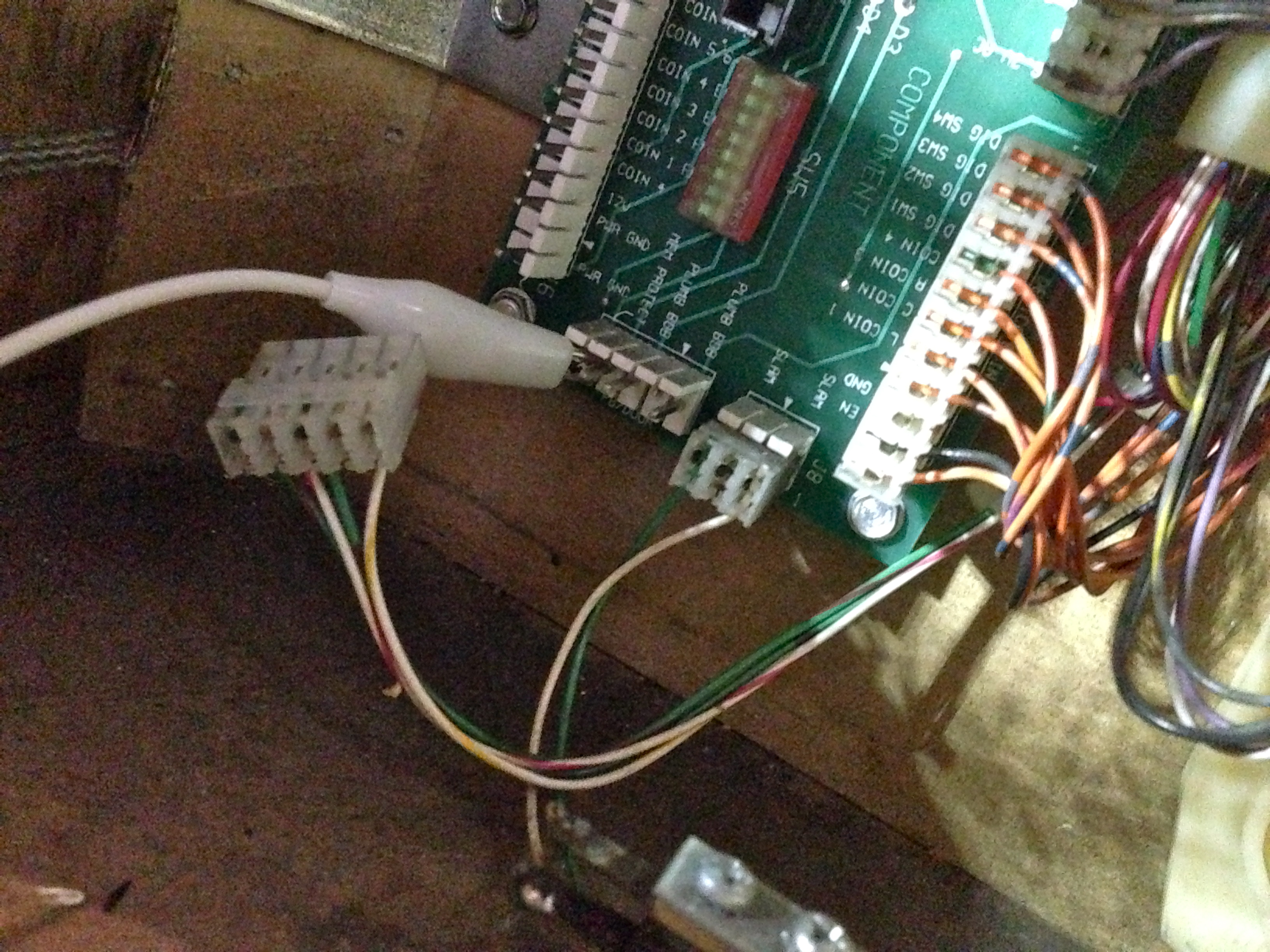
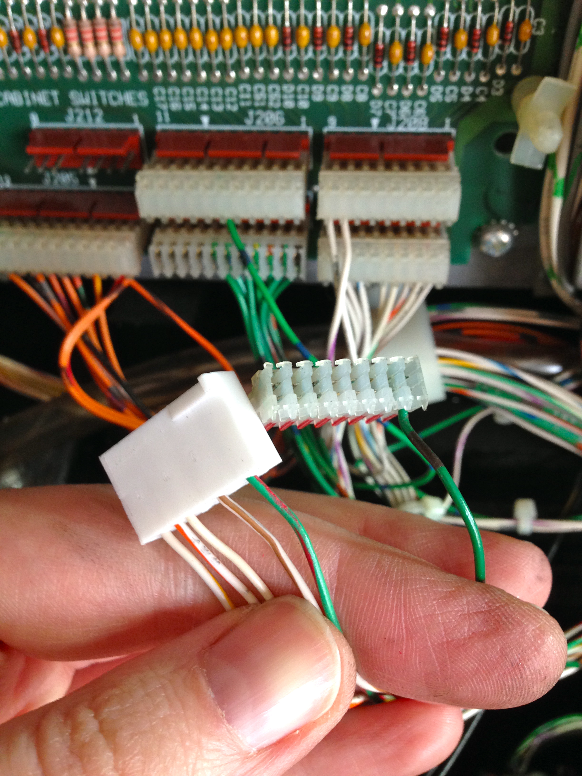
The next link up the chain is a gnarly one. It’s the harness that runs from the Coin Door Interface Board to the CPU Board. It’s about eight feet long, and buried in a huge morass of wiring inside the machine. Luckily, the schematic tells us which connector on the CPU board is the other end of this harness, so we can check that and determine if there’s something in between that is failing.
Well, here’s where the story comes full circle. As soon as I found the connector on the CPU board for the other end of that harness, I laughed out loud. It was the one where I’d found all that corrosion just the other day. This was surely our culprit. Nothing causes an intermittent connection quite as effectively as battery electrolyte corrosion.

It would be nice to be sure this is the problem by bypassing the harness and testing again. However, because this is a switch matrix harness, all the wires in it need to remain connected at all times (unlike the tilt-bob situation earlier). That means to bypass this, I’d need to effectively build a new harness. That’s more work than simply replacing this connector, so I’m opting to do that and see what happens. I think we have more than enough evidence here to suspect this connector, so this isn’t a blind attempt at a repair.
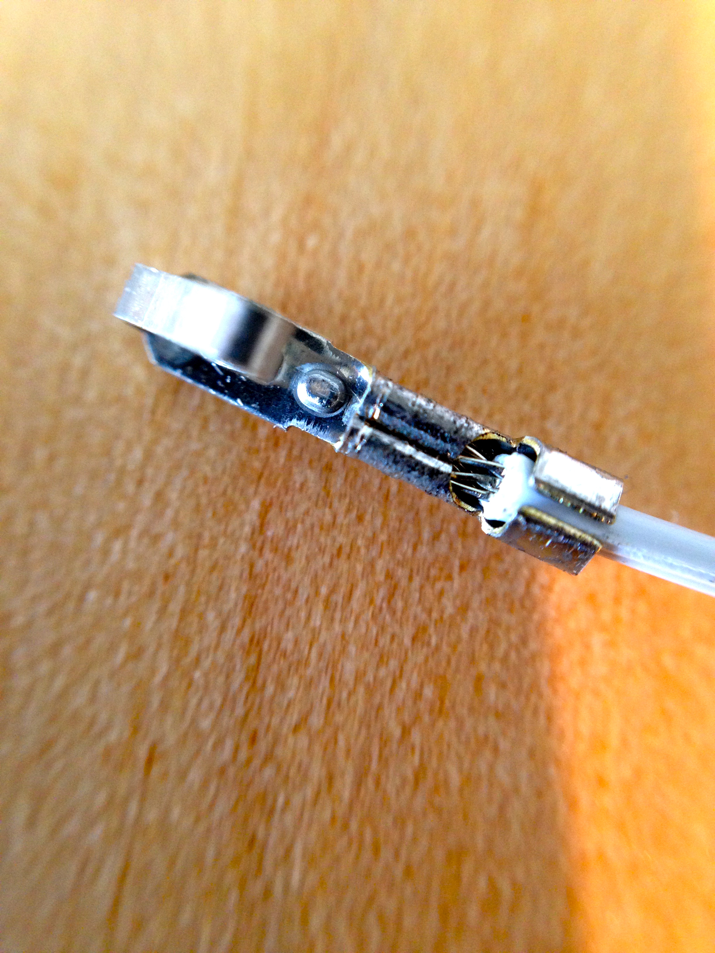
The connectors used in these machines are called Insulation Displacement Connectors (IDC). They are great for manufacturing, because they are very fast to assemble. The connector has a V-shaped cutting blade inside each pin, and the wire is pressed into it from above. The V cuts the insulation, and bites into the strands of the wire, forming a solid, gas-tight seal at two points. They are a good compromise of cost vs. reliability, but they are no match for corrosive chemicals from a leaking battery.
Rather than put another IDC connector on there, I’m opting to replace it with the equivalent Molex. Molex connectors are strong, very reliable, and very serviceable. They’re more work to put together than IDC, but that’s not a problem for a hobbyist like us!
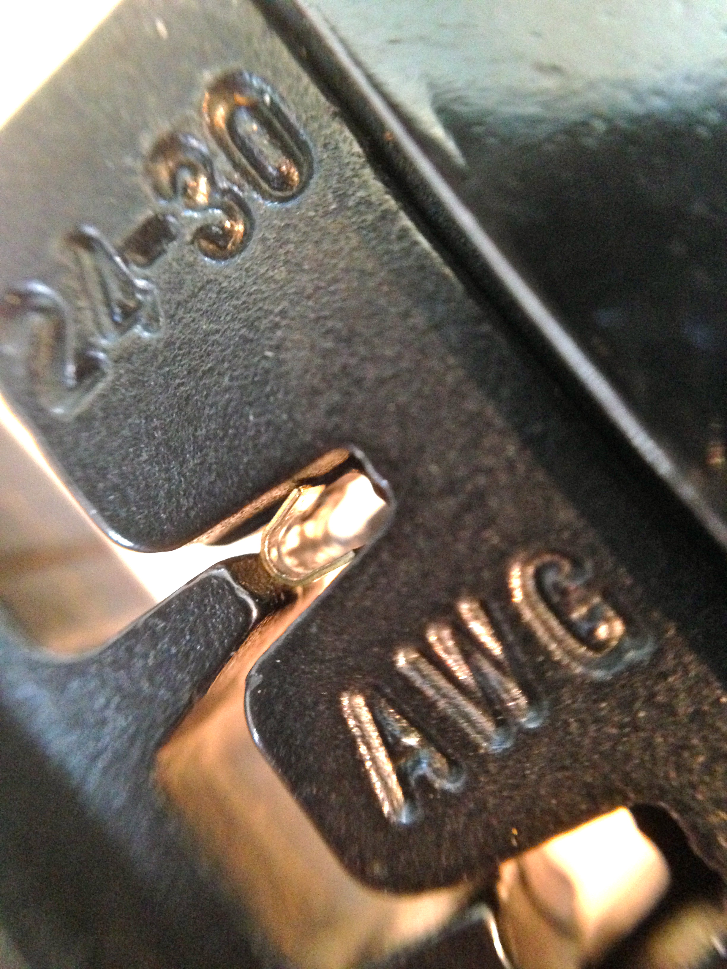
To work with Molex, you will need a Molex crimper. Nothing else will do. I would go one step further and say you must have a ratcheting crimper. Doing this with anything else is seriously asking for trouble on connectors this small. Run, do not walk to your browser, and buy the Tool Aid Ratcheting Crimper with interchangeable dies. You can get it on Amazon, or elsewhere. It’s very reasonably priced, great quality, and the entry-level kit comes with all the basic dies you’ll ever need. On top of that, the Tool Aid people have awesome customer service. Do us all a favor and support businesses like that! To crimp square Molex pins, you need Tool Aid die 18937, which is not included in the basic kit, but can be ordered separately (from Amazon, or direct from Tool Aid, with a phone call). Tooling yourself up for Molex is well worth the small upfront investment. You can build harnesses for all manner of projects very cheaply once you have the crimper. My Tool Aid crimper has singlehandedly wired two race cars, my arcade control panel, parts of my house, and countless other things. It’s one of my favorite tools, and if you don’t buy one, I’ll kick a puppy right this minute. Don’t make me do it!
Molex crimps are very strong and very reliable if done properly. Technique and the right tool are everything here. Do not take any shortcuts. Take your time, use the right tool, and it will go very smoothly. The final connector will outlive whatever machine or device you put it in.
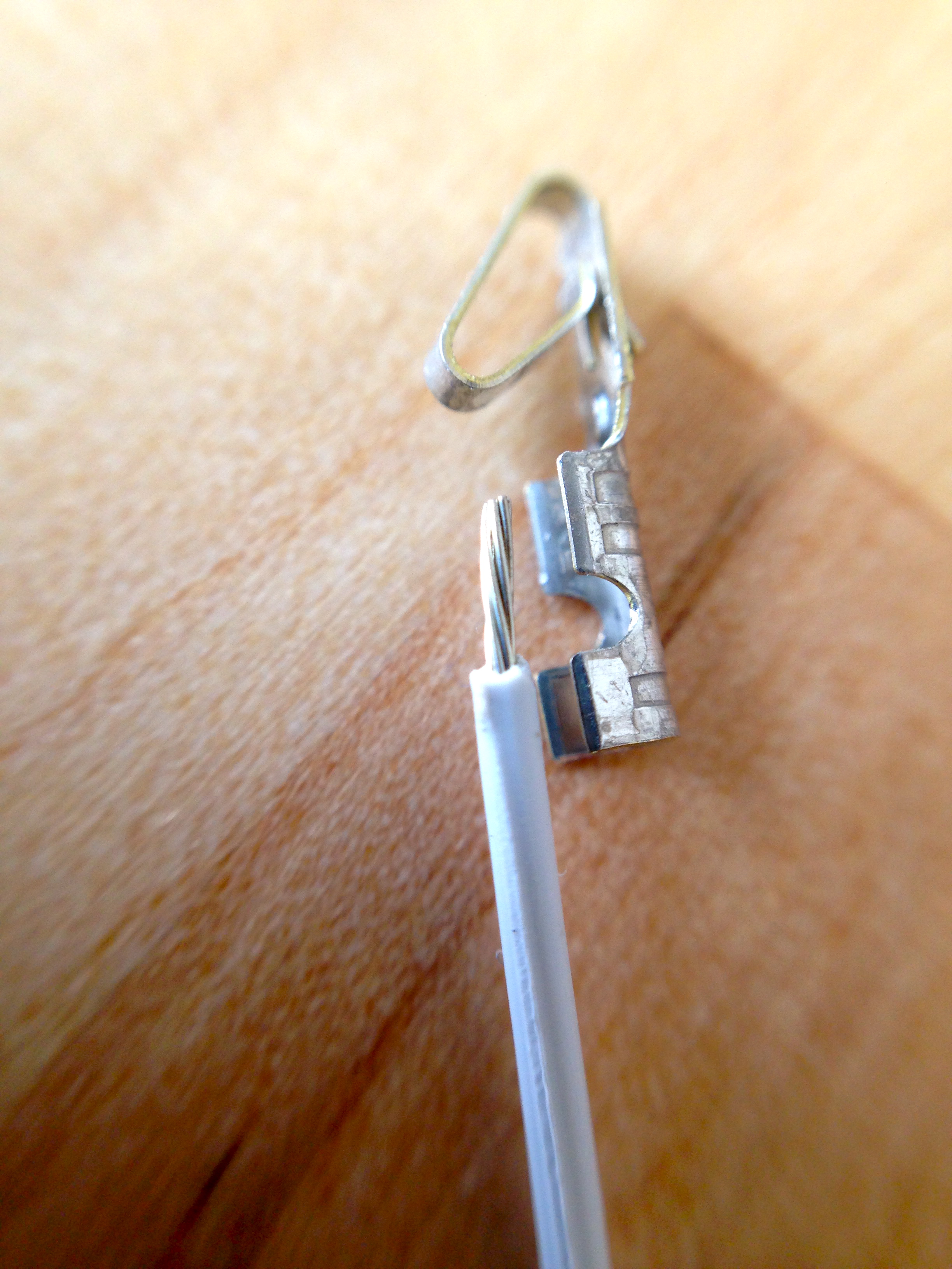
Do some practice crimps if you’ve never done Molex before. Everything has to be lined up exactly right for it to work. This is also why you want a ratcheting tool. You can place the pin in the die (as shown above) and ratchet down a couple of clicks to hold it in place. Then insert the wire, and ratchet the rest of the way. Otherwise you need three hands, and have little hope of getting a well-aligned crimp. Furthermore, the crimp has to be just the right tightness. Too loose, and the connection isn’t gas-tight. Too tight, and the wire will be weakened and fail prematurely. The ratcheting tool crimps perfectly every time with no guessing.
Note that solder is not (and should not be) involved in any part of this process!
So where do you get all this Molex stuff, anyway? I find it easiest from Mouser. Mouser’s site can be very intimidating, but here are the part numbers for the relevant Molex bits. Put these into the search box to get what you need. The bold “12” in some of the part numbers is the number of pins in the connector. It’s always two digits, so substitute “08” for 8 pins. The larger 0.156″ stuff is used on power connectors, and 0.100″ is used on logic signals.
- 0.156″ connector housing : 26-03-4121
- 0.156″ locking headers (breakaway) : 26-48-1155
- 0.156″ pins (Trifurcon, the good ones) : 08-52-0113
- 0.100″ connector housing : 22-01-3127
- 0.100″ locking headers : 22-23-21221
- 0.100″ pins : 08-50-0114
If you can’t get enough technical information on the physics of mechanical connectors, this site has even more detail. Note that some of the Mouser information is out of date, but the general information there is great.
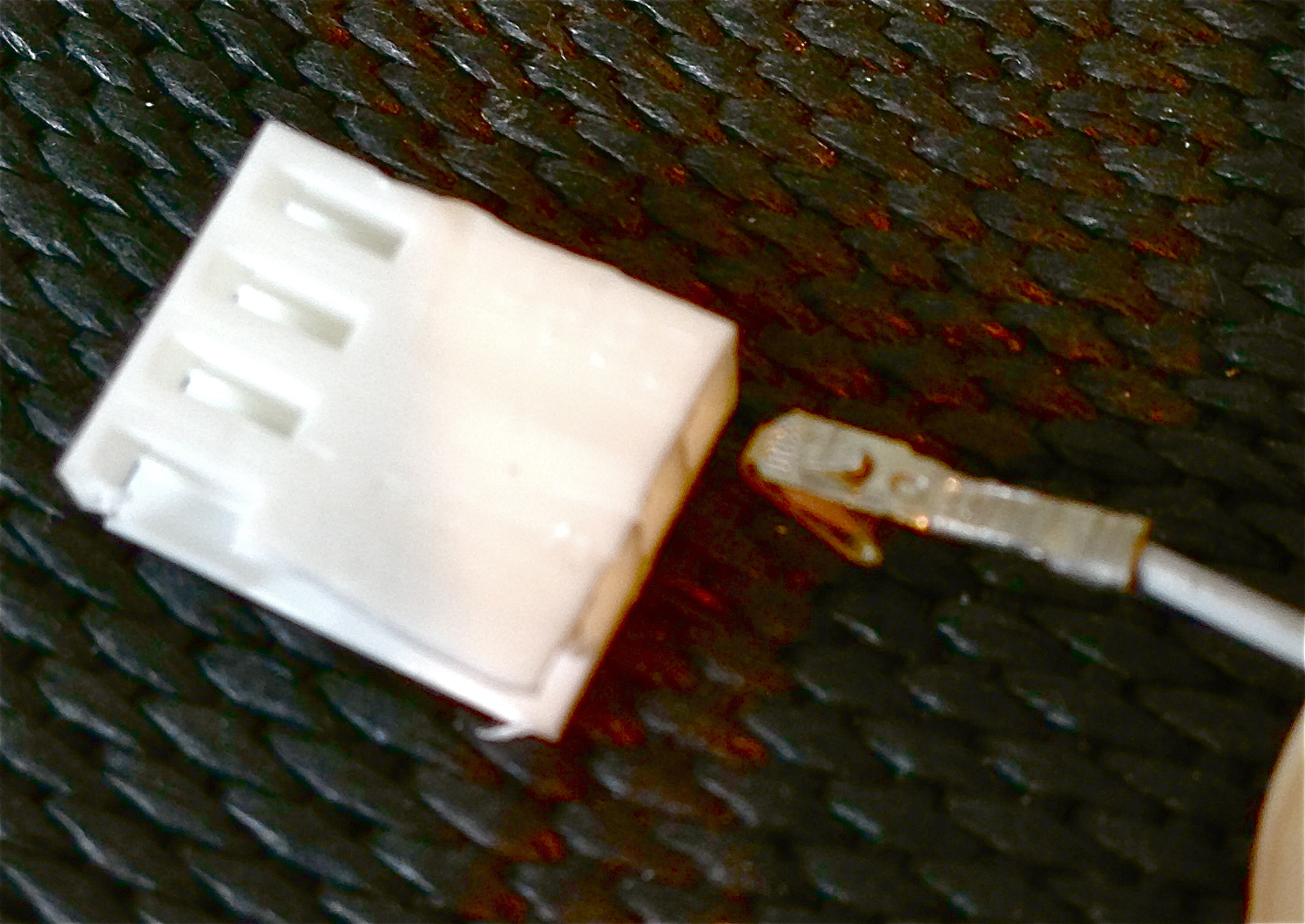
Once the Molex process is understood, it’s simply a matter of pulling the wires out of the old IDC connector, cutting off any damaged end on the wire, stripping, crimping, and inserting the new pin. Move one wire over at a time to make sure nothing gets mixed up.
I had a little bit of trouble with wire length on this job. A couple of the wires in the harness were barely long enough for the old connector, and putting a new one on makes them a bit shorter still. I had to loosen the harnesses a ways back from here to find some slack. Hopefully I won’t have to do this again, because there’s no more slack to be had. I suspect this connector had been worked on before, because normally there’s enough slack to do this kind of job a couple of times. If it needs doing again, wires will probably have to be extended.
There was some corrosion on the header pins as well. There’s a judgement call here- do I pull the CPU board and replace this header? This is a question of risk-reward. There are a dozen connectors and other things attached to that board. Pulling them all out to extract the PCB risks causing damage to something. The corrosion on the pins was very minor, so it may not be worth the risk to pull the board. Not to mention, there’s risk with desoldering and resoldering a header. I could damage something on the board that would have been fine if I’d left well enough alone. I opted to leave the old header in place, clean it up, and see how it goes for now. If the connection is still intermittent, I’ll take the next step and pull that board.
Well, the good news is, Johnny now seems to be fighting fit once again. I left attract mode running for 20 minutes with no signs of interlock warning, and I played several games as well. There’s no sign of any trouble at all from that connector now. Huzzah!
videos: “Embedding disabled by request”
Whoops! Thanks for catching that. Should be fixed now.
Hi Quinn,
Great troubleshooting and narrative; thanks for sharing.
Thanks also for the lesson on Molex connectors.
Is the Molex connector you used 100% mechanically compatible with the header? It looks as if the original header has some clip or latch to keep the connector in place.
Cheers!
Great question! Yes indeed, these connectors come in locking and non-locking versions. The locking ones are identical to the existing locking mechanism of the header on the board. The header is part of a system that includes IDC and crimp-pin options for the mating connector.
Something that can prolong Molex connector life is a type of automotive silicon grease that we often put into spark plug boots to make them easier to remove (I use this stuff on my drag car, since the plugs are constantly being removed for one reason or another). This is not the white stuff that one would use between a semiconductor and a heat sink. It’s an almost clear product that might be available at your local auto parts emporium.
Prior to mating the connector, use a Q-tip to put a small amount of the grease into the female pins. The key phrase is “small amount.” That little bit of grease will prevent corrosion of the tinplate pins and also aid in making solid contact. Give it a try. 🙂
Yes, I know the stuff you mean- dielectric grease, yes? I used it quite a bit on my Jeep. Off-roaders fill all their electrical connectors with it because it keeps water and mud out of them, particularly when fording water deeper than lighting harnesses (which it often is when I’m driving. 😉 ). Keeps you from blowing fuses every time the tail lights go under water, and long term, it prevents corrosion which plagues old 4×4 electrical systems. Old American cars weren’t very concerned about sealing things.
I never thought to try it on molex connectors. Good idea!
Quinn,
An OSI vintage guy told me about Nyogel 760g, those computers used molex pins for the backplane. Makes the connectors work without too much force, and a little bit goes far. Flashlight places like lighthound carry it.
Cheers. ?;-)
Old American cars weren’t very concerned about sealing things.
Not to mention the quality of connection in some parts of the electrical system.
When electronics started to play a key role in engine operation management, it soon became apparent that tinplate connectors could cause random failures, especially in control circuits operating in the milliamp range. I recall back in the 1980s when GM introduced “fuel injection” to their production cars (we call their throttle-body injection “electrically controlled leaky carburetors”) we could often fix maladies by simply unplugging and replugging connectors. As more electronics invaded the engine compartment, more connectors would add to the woes.
My 1994 T’Bird had a periodic problem where it would set codes related to the mass airflow sensor. I finally dug into it and found that the real culprit was the tinplate connector used on the sensor assembly. So about once every six months I’d unplug the MAS and plug it back in. The problem never came back. 😉
Seems like it took everyone except the Japanese (and eventually the Germans) a long time to figure this stuff out. One of my team’s race cars is British (a 1974 Lotus Elite), and it has the most poorly designed electrical system I have ever seen anywhere, in anything. Like, astonishingly so. Every single connector, junction, fuse holder, relay, lamp socket, and switch is total garbage. It’s a source of constant hilarity to the team when we crack open another part.
I ended up rewiring the entire car from scratch myself. This stuff wasn’t reliable in street cars when it was new, never mind on the racetrack 40 years later.
Yes, I know the stuff you mean- dielectric grease, yes?
That’s the stuff. It has 101 uses. 🙂
It’s strange that those door switches are not both wired. Usually those would be wired in series, at least in my profession, which is working on high voltage power supplies (25kV and up) for microwave RF tubes. The reason is that switches sometimes fail, and sometimes they fail “good”, as when the contacts inside weld or stick together and then you have interlocks that think everything is “safe” when it is not. Two switches, while “redundant” (thats the idea), are better than one. We have cabinets that have those exact switches and those kinds of brackets, so maybe when they made those pinball machines, they just bought those off the shelf and used them as-is?
And for your battery box, I heartedly suggest ultimate lithium AA’s! They last wayyyyyy longer and I’ve never seen them leak, even in extreme conditions.
I love your blog and your sense of humor is dead-on. Awesome stuff!
-Ryan
Thanks for writing Ryan- those are good insights.
Regarding the switches, I’ve learned more since this was written. It turns out the lower one is just a logic switch for the CPU to know the door is open and it should flash the warning. The upper switch is supposed to be the physical disconnect of the high voltage. The loose connectors I mentioned are supposed to be routed through the primary power supply in some fashion to do the job of actually cutting the power. There seems to be no way to do that on my game (the connectors don’t reach anywhere or match anything), so perhaps my power supply has been modified or something. I verified that indeed the high voltage is still active when the door is open. One more example of why we should never assume a high voltage source is safe. I’ll be looking into this further to see if I can make the interlock properly functional again.
And yes, lithiums AAs are a good idea as well. A lot of pinball people use them for the exact reason that they do not leak when they get old. Next time I replace these, I’ll be putting those in, I think.
I’m sure you already know about this stuff, but I’ve had a can of Caig’s DeoxIt contact cleaner/ connection enhancer around forever and swear by it. You use a tiny amount and it lasts forever, and really works wonders on old (or new) contacts. I think it was originally developed for the military to reduce contact resistance and maintain a good connection, and was eventually picked up by the audiophile folks, but now is more commonly available.
I use it for things like sporadic battery connections and the like. just a dab will do it.
It is no good for scratchy potentiometers, but works on everything else.
The company seems to have considerably expanded their product line since i got my can, but the DeOxy is the one i have experience with.
http://store.caig.com/s.nl/sc.2/category.188/.f
thanks for the interesting pinball writeup!
Matteo