Alliterating our way to success.
So far our little Wobbler has a crankshaft, main bearing, piston, and cylinder. However, it’s currently a bucket of parts. It’d be nice if we had, you know, something to which we can attach them. It would be even better if the result was vaguely steam-engine-shaped.
The frame for Steve’s Wobbler is a pretty straightforward piece. All the plumbing is done by drilling passages through it, and it also supports all the shafts. It’s a great piece to stretch our bench layout muscles, since it’s easy to make but precision is important. The frame establishes the relationships between all the moving parts, and if something isn’t right, we’re likely to get binds, leaks, or other conditions that will make our engine have a sad.
The frame is a single piece of ⅜” x ¾” brass bar stock. As is tradition, let’s start with the drawings.
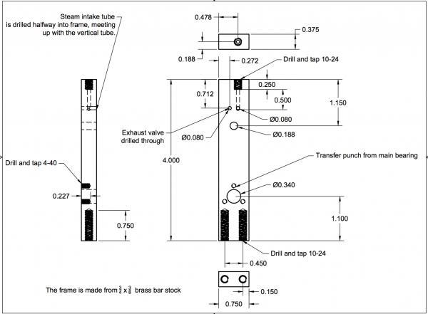
The main thing to watch for when reading that diagram is that the valves are on the correct sides, and the main bearing mounting holes are correct. If you reverse the valves, the engine will run the opposite direction. If you get the main bearing mounting holes on the wrong side, you won’t be able to assemble the engine.
You might ask why I call out those particular mistakes? Well, because they are both mistakes I made. The first copy of this engine that I built went just fine, but for some reason I got all turned around in my head when making the second one. I did in fact reverse the valves, which is harmless enough. The second engine runs backwards. No judgement there. For the main bearing holes, I was able to salvage the situation by drilling and tapping them all the way through and installing the screws from the other side. That saved me remaking this entire part, at the cost of some aesthetics.
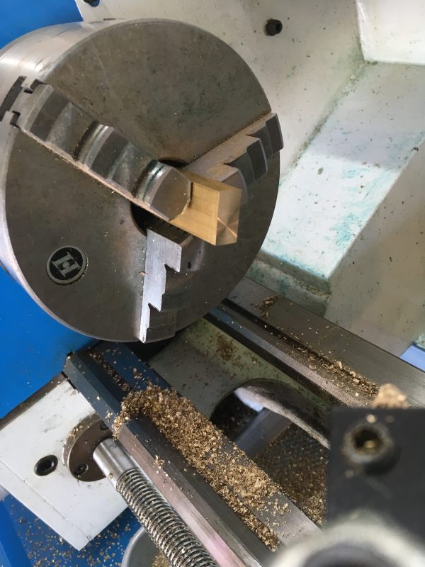
Okay, we’ve bent our minds around the drawings. Let’s make some chips! To start with, we want to true up the ends. This thing stands on its end, so that needs to be very square. This is easy to do on the lathe. Lathes aren’t just for round parts!
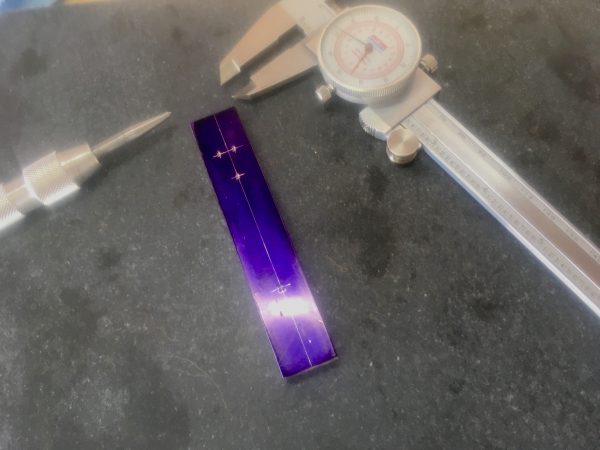
With both ends squared, its off to the layout bench. This layout work can be done in various ways- you might use calipers to register on the edges of the stock, or you might use a height gage on a granite surface plate. Resist the urge to do it with just a straight edge and your eye. You won’t get things aligned precisely enough. Center punch all the holes to be drilled.
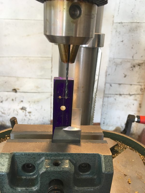
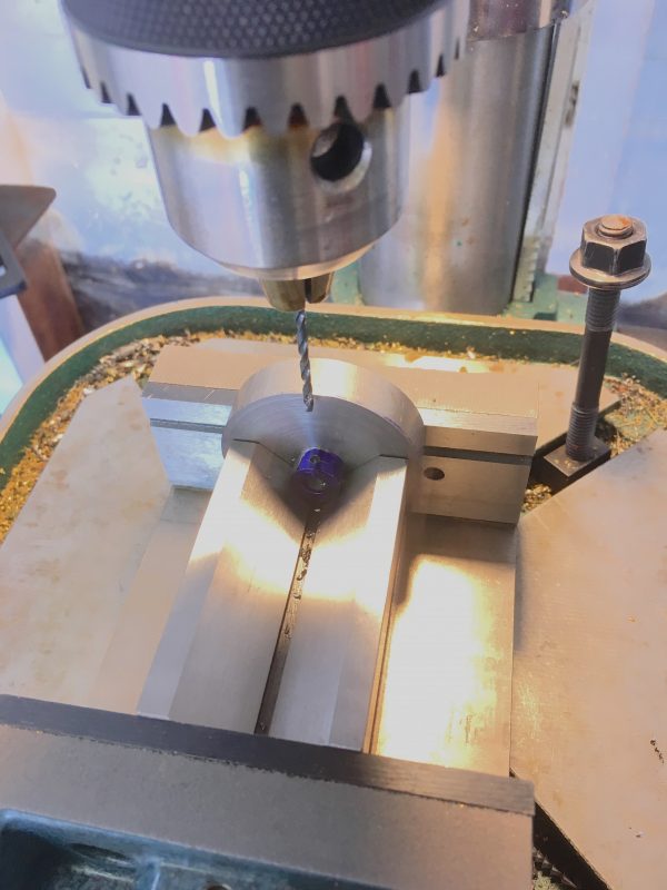
Now it’s off to the drill press. The crankshaft and cylinder pivot holes need to precisely dimensioned and square to the face, so drill undersize and ream them with the press. The valves are less critical diameter-wise and just relying on the drill to dimension them is acceptable. Note that the positions of the valves is very important indeed. Triple-check your layout on these!
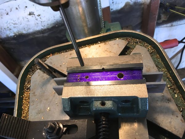
For the intake valve, be careful not to drill through. It should stop at the halfway point of the thickness of the frame. A little further is okay too, as long as it doesn’t go through. We’re building a 90° pipe inside the frame, effectively. The depth-stop on your drill press is your friend here.
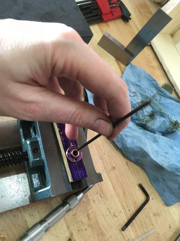
With that done, we can prepare the main bearing mounting points. These are much easier to transfer punch rather than relying on laying out two perfectly matching three-bolt circles. Simply install the bearing we made in the frame, and tap tap tap.
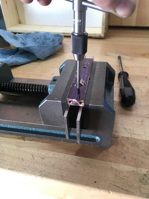
Not shown in the pictures are the drilling and tapping of the mounting holes on the bottom, and the steam intake fitting on the top. Those are easy jobs, though. The frame is pretty much done, so let’s move on to the flywheel.
Flywheels are interesting things from a physics perspective. They are very much analogous to a capacitor in electronics. Much like a capacitor can be used as temporary electricity storage to smooth out momentary drops in power, the flywheel acts as a kinetic energy storage unit. Reciprocating engines are pretty rough and inconsistent in their power delivery. In a single-acting steam engine like we’re building here, there is only smooth power application for half the travel of the piston. A four-stroke gas engine is even worse, delivering power for only ¼ of the piston’s travel! Multiple pistons can help smooth this out, but the situation is still pretty grim. Best-in-class is probably the double-acting steam engines pioneered by James Watt, which make power on every stroke in both directions of piston travel. That’s a trick internal combustion engines can’t manage (although Lenoir and Körting tried). Still though, it’s a reciprocating engine with non-linear gas expansion forces pushing it around, so anything you attach to that is going to get rattled to pieces in short order. Even worse, for a simple design like this wobbler, the engine probably won’t even stay running. It needs the momentum of the flywheel to get it through the dead spots in the piston and valve cycle.
But wait, there’s more! During the non-power strokes, the engine isn’t twiddling its thumbs. It has work to do moving valves around, pushing exhaust gases, and in our case swinging the dead weight of the cylinder around. Energy is required to do all this housekeeping, and the flywheel acts as a loan from the power stroke to the future. Of course, the flywheel has inertia of its own, so this energy loan has interest we have to pay back with more fuel. There are no free lunches. Flywheels are remarkably efficient, though. So much so that they are in use for large scale grid storage, and Porsche’s hybrid race cars in LeMans are using them in place of chemical batteries.
There’s yet further optimization we can do. It turns out that the mass near the middle of the flywheel isn’t helping very much. It’s the weight around the edge that is doing all the energy storage and transfer (because it has the velocity). The closer to the center you go, the more that mass is just acting as dead weight. That’s why flywheels are generally spoked. That’s a bit fancy for this simple engine though, so we’ll accept the relative inefficiency of a solid design.
Alright, enough theory. Let’s make a flywheel. To the drawings!
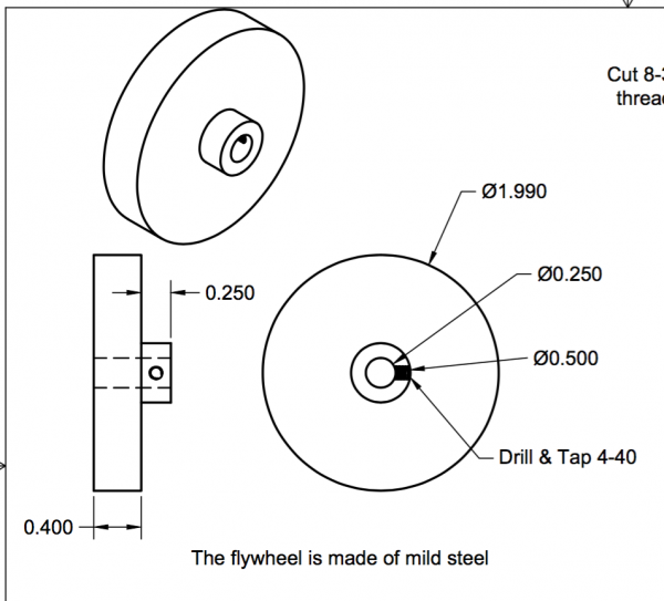
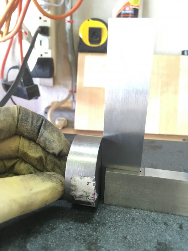
To start with, we need a chunk of stock. Generally speaking, with flywheels, the heavier the better. We’ll use steel here, but lead or cast iron would also be good choices. Brass and aluminum generally don’t make great flywheels. You need some oomph. Some heft. Some “je ne sais quoi” of mass. Time to heave the 2″ leaded steel bar off the junk pile. Lift with the legs…
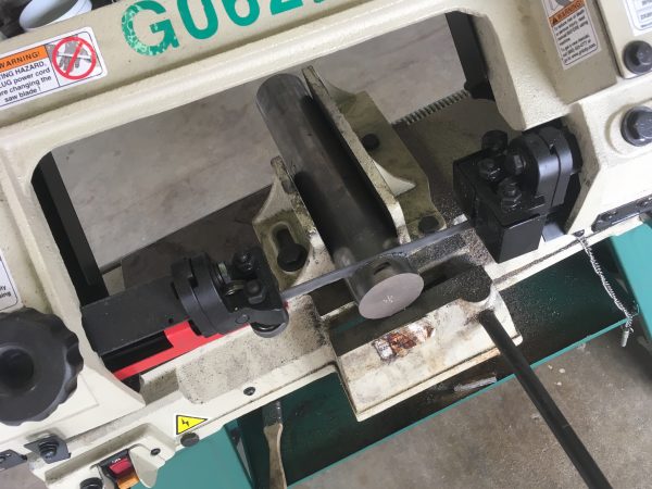
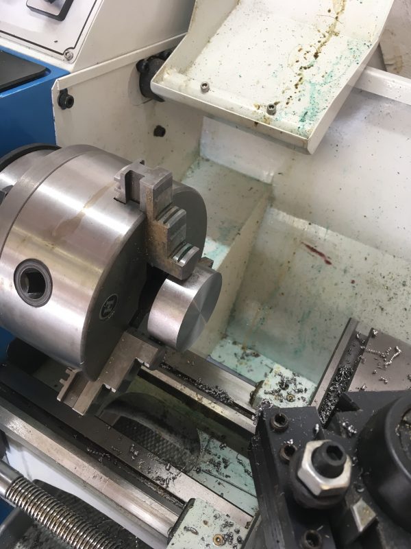
No matter how you slice it, the ends will need squaring up. To the lathe we go.
With one side flat, we can now flip it around and make the other side parallel (and reduce it to the overall thickness we need).
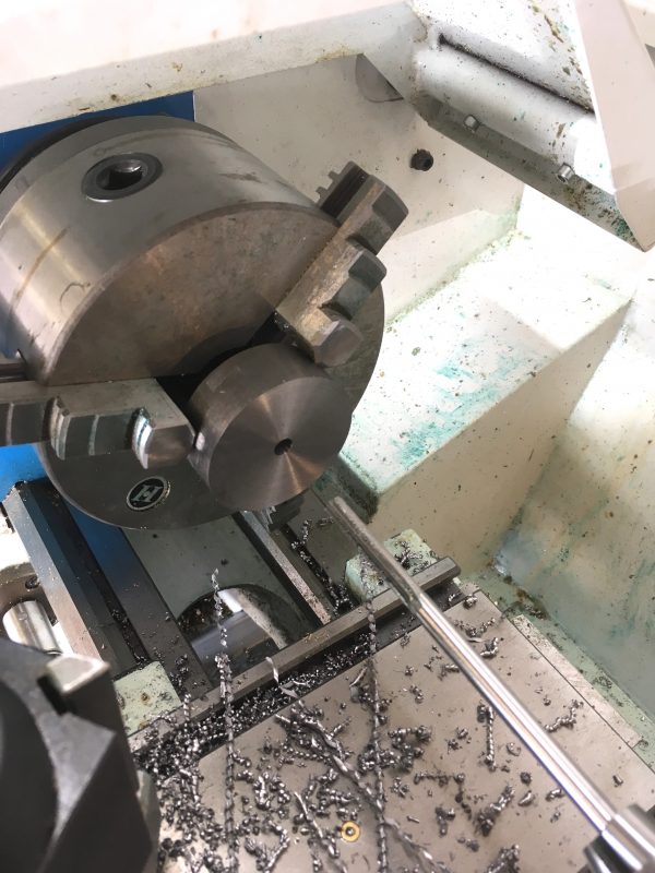
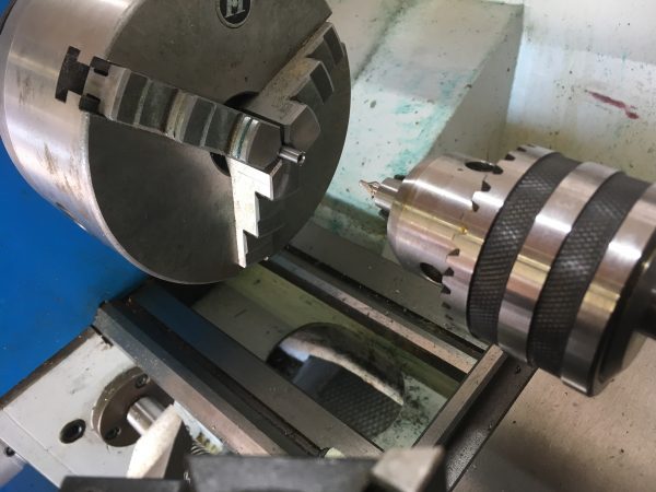
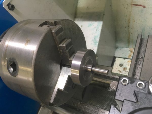
Next we want to drill and ream the mounting hole that the crankshaft goes into. Concentricity is important here, so don’t remove the piece from the chuck.
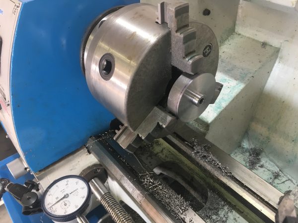
To cut in the boss, we’re doing basically a very deep turning operation. You could also view it as a large facing operation. There’s a gray area there between facing and turning whereby either technique will work fine. The main thing is to make sure the new inside surface created when we cut in the boss remains parallel with the faced back surface of the flywheel.
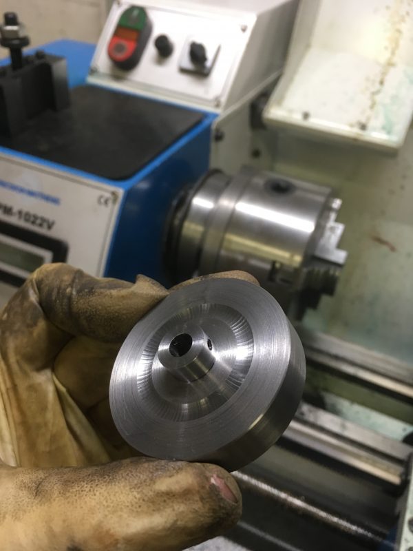
The flywheel will be mounted to the main crankshaft, and it will need a setscrew for that. Off to the drill press to cross-drill and tap for it.
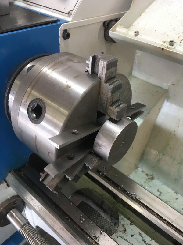
So far so good, right? Well, we have an interesting challenge next. We need to turn the outside diameter to clean it up. However we didn’t do this before because we also need perfect concentricity with the hub. This is important for a flywheel, because it needs to be balanced in order to run smoothly. It’s a big spinning mass, and the better balanced it is, the better the engine will run. The four-jaw chuck won’t save us here, because we can’t hold the outside of the piece any more. We need to turn it all off. In fact, the work holding method we need is the very oldest of them all- turning between centers.
Imagine it’s the 1700s and you’re trying to turn a piece of metal to be very round. Your materials and tools kinda suck so you can’t make something like a chuck without massive run out. Even your drive spindle is bad and you can’t rely on that. It’s likely driven by a foot-treadle and made of wood. Maybe a donkey is involved. It’s a wild scene, but it ain’t precise. Instead, you hold the piece between two sharp points. Then it doesn’t matter how much runout is in the rest of the lathe- the work will spin perfectly true no matter what. Simply clamp something to the work so you can spin it under power, and away you go. The same technique works today, and it is still the most precise way to guarantee roundness and concentricity.
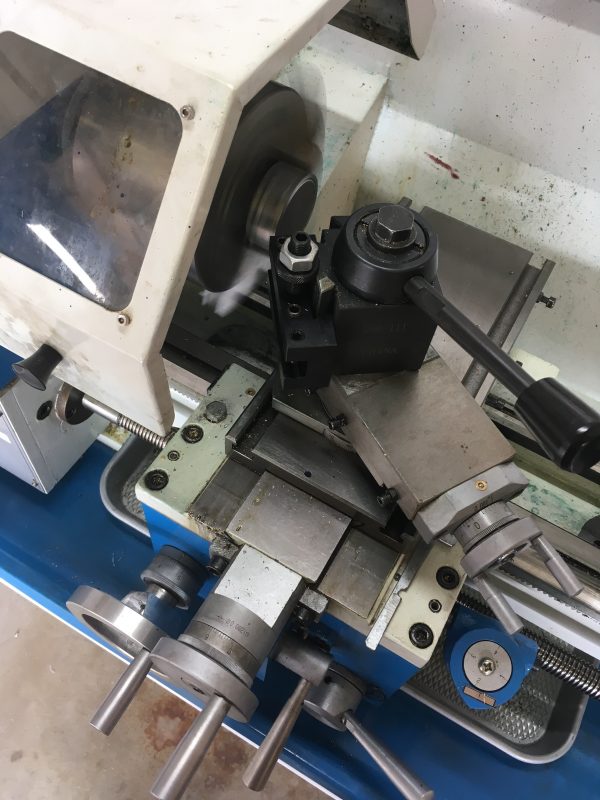
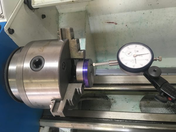
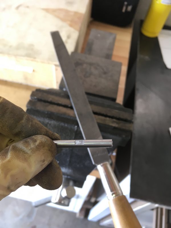
To start with, we need a mandrel to hold our flywheel. It can’t be held between centers the way it is.
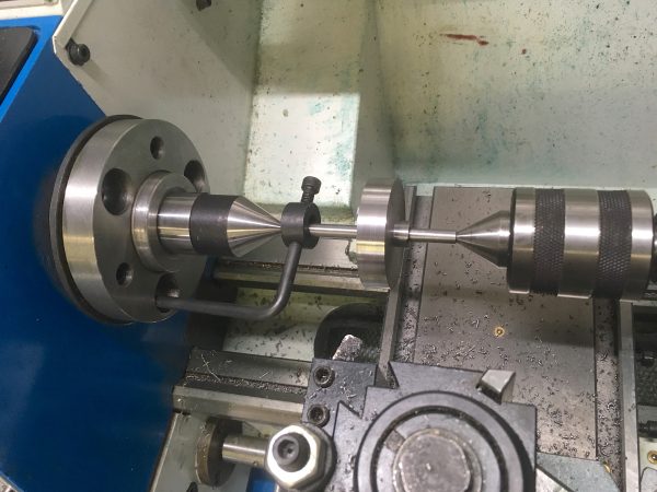
With this setup, the entire outer surface can be turned, and we know the result will be extremely concentric with the hub.
Well folks, we’re getting perilously close to having all the parts for an engine. We have a few more bits and bobs to make, and a fair amount of fit-up to do (nothing ever just works), but we’ll have this engine running very soon.
A quick thank-you to all my Patrons who stuck with me during The Troubles of the fee changes (and unchanges). Thanks also to all the new folks who signed up as a result! Voting with your wallets for the content that I produce is very flattering and greatly appreciated. Many folks have also taken advantage of the improved Paypal option as well. Since that’s a one-time donation, I hope all the non-Patrons will consider clicking that Paypal button for each post.
Thanks again, and stay tuned!
A (belated) Merry Christmas and Happy New Year, Ms Dunki! (I assume a “Mrs” there would be incorrect, but — assumptions are dangerous, please correct me if I’m wrong — just not with the business end of your welder, please! 😛 )
I have to say I’m enjoying this series. Can’t follow along IRL — I lack a lathe (and the funds for one), and I kind of like having long hair (lol) — but hey it’s fun to watch. I love steam engines, old technology of /any/ significant sort, and almost all varieties of homebuilt crap (regardless of quality).
I can’t wait for the next installment 😀
Hey thanks! It’s great to know people are enjoying it. I get a lot less comments on the machining and shop-related posts than I do on the electronics stuff, so I’m concerned people don’t like them as much. It’s hard to say.
I’ve noticed that (the comment phenomenon). I think it’s unfortunate… both topics are quite interesting to me, personally – but (of course) I can only speak for myself. I would hope that most people who come here can say the same… but I dunno, I’m only me 😉
I really appreciate those machining posts as much has the electronics topics. They are fascinating.
I don’t know for other readers, but for me not commenting as much comes from knowing barely nothing about the subject : I have nothing to contribute, and am not even confident enough to even discuss it.
If only everyone was sufficiently humble to not comment on things they don’t have any expertise with. Very civilized of you.