Did we make a steam engine or a pretty pile of scrap? Time to find out.
In the previous installments in this series, we built most of the major pieces of our little wobbler steam engine. We just have a couple of accessory parts to make, and then we’ll be ready for fitting things together.
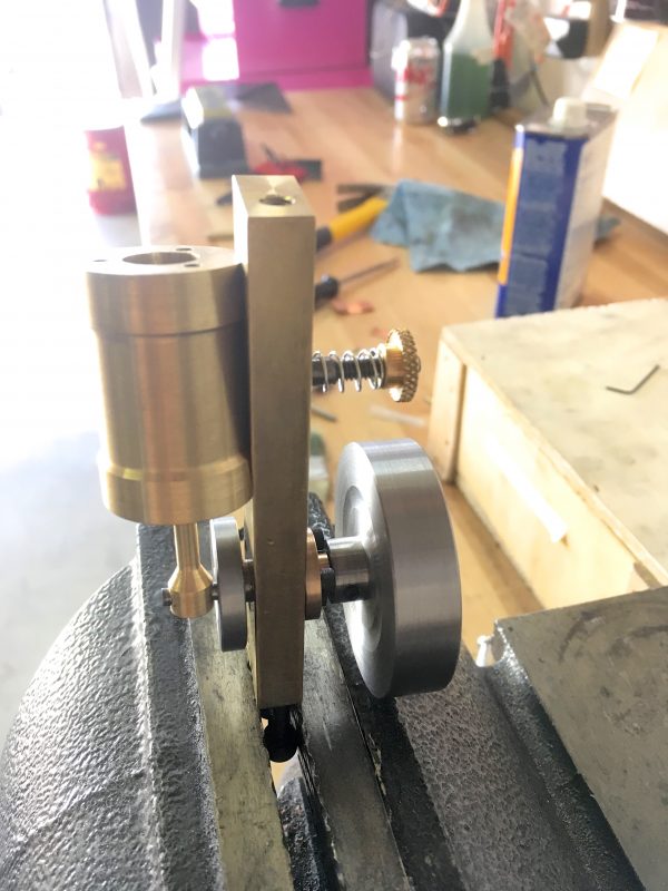
The second-last part we need is the tension adjustment knob for the cylinder pivot. This allows us to achieve a balance between steam-seal at frame/cylinder, and still allowing smooth movement. As is tradition, let’s take a look at the drawing first.
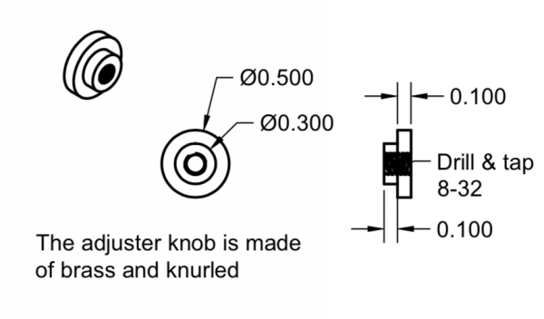
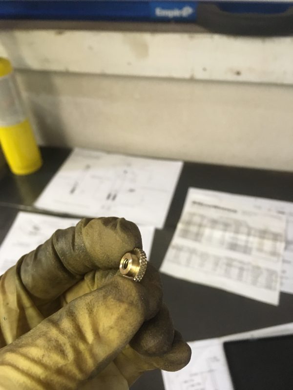
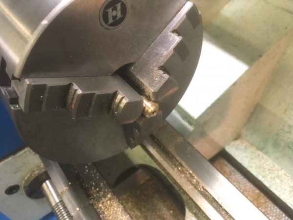
The last step we want to do is knurl the outer diameter. Knurling is a machining technique to create a 3D pattern on a surface so that human meat sticks can grasp it easily. A special knurling tool is used, which generally consists of a pair of wheels, each with half the pattern on them. You apply pressure to the stock with these wheels, and they form the pattern as the stock turns between them. Knurling is a forming operation, not a cutting operation, which means it requires a lot of force. Cutting knurlers do exist, but they’re hard to find and expensive.
Getting good knurls is one of the trickier lathe skills, but there are basic things you can do to jump ahead on the learning curve:
- Get the outer diameter right for your knurling tool. Hardly anyone mentions this in online knurling tutorials, but it’s critical. LittleMachineShop has a terrific online knurling calculator that I refer to often. You need to know the pitch of your knurler in points-per-inch. If you’re unsure, roll one of the wheels on a piece of paper, and count the peaks in one inch. It’s probably 21, which is by far the most common.
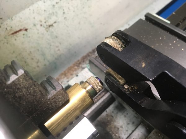
- Your quick-change tool post probably came with a knurling tool with the two wheels mounted rigidly to a shaft that goes in the tool post. This is called a “bump knurler”. The first and most critical step in using one of these is to throw it in the trash and go buy a “scissor” style knurling tool. Because knurling is a high-pressure forming operation, you want the pressure to be balanced on both sides of the stock. Bump-knurlers apply all the pressure on one side, which is very bad for the bearings in your lathe. Don’t use them.
- Setup matters a lot for knurling. You need to work close to the chuck and align things so that the clamping pressure is centered on the stock. Lock everything down on the carriage.
- Use lots and lots of cutting fluid.
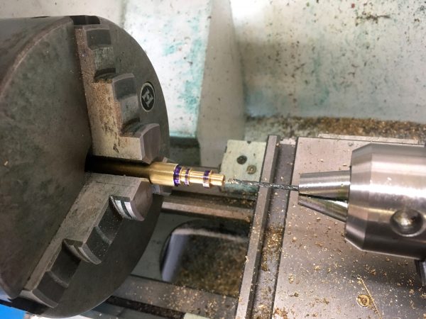
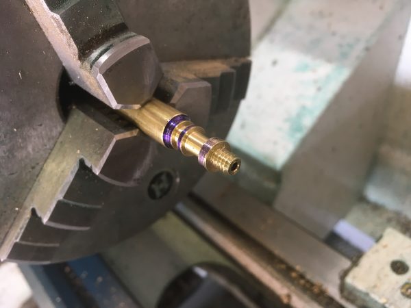
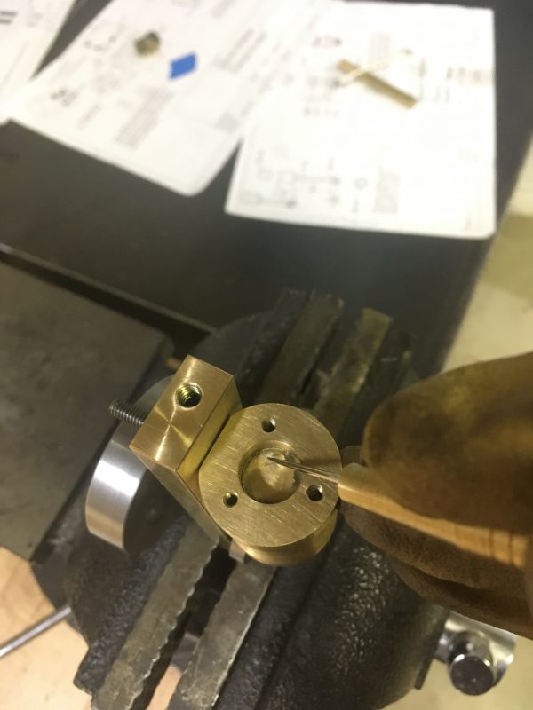
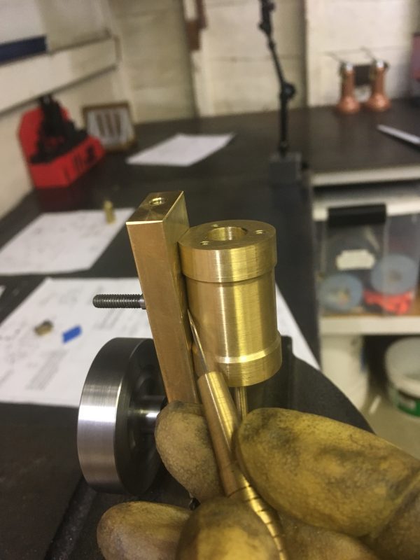
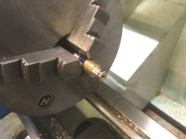
The final (yes, final!) piece we need to make is a fitting to attach our air compressor to the steam inlet. We’re going to run this engine on compressed air, so we need a way to get the air in there. To the drawings!
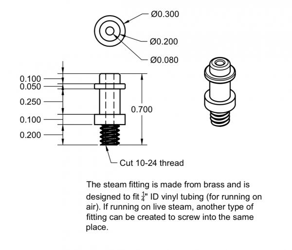
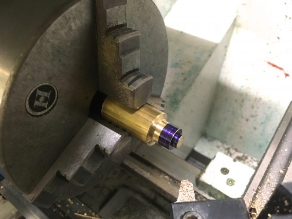
As usual, we start with a piece of stock of generous length, and face the end.
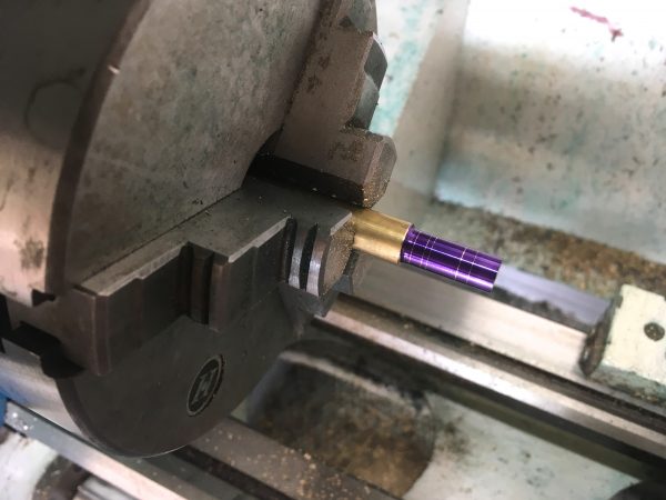
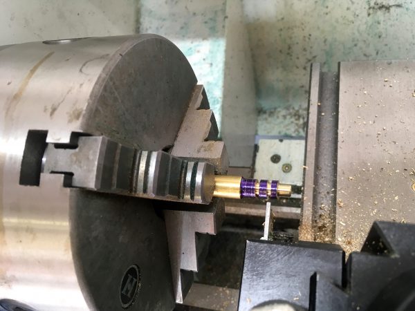
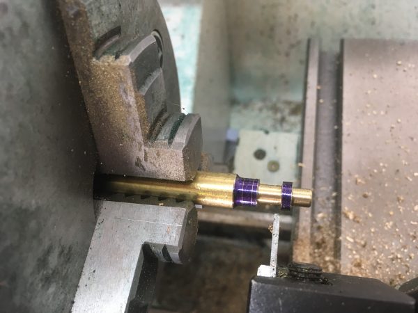
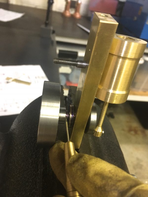
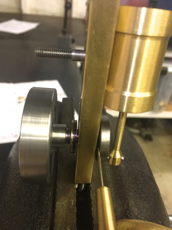
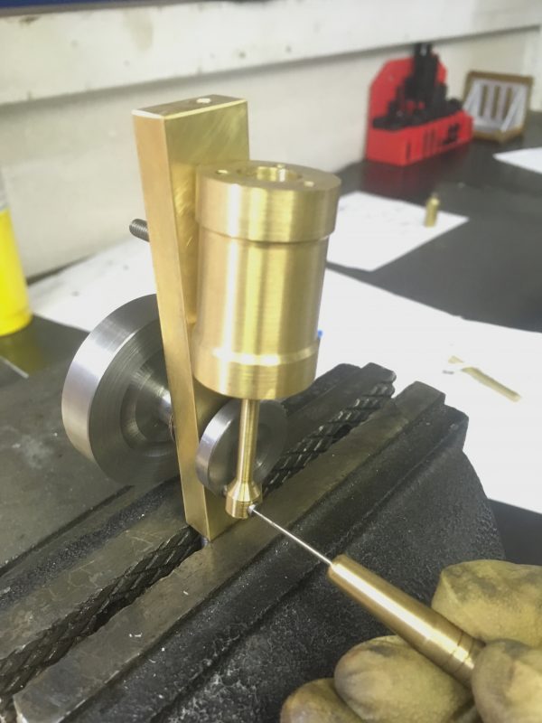
This part has a lot of narrow ring-shaped features with sharp transitions. Making features this small can be tricky, but a cut-off tool is your friend here.
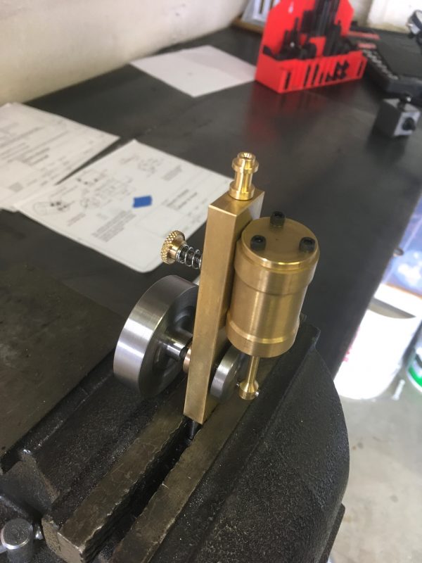
Okay, let’s do some fit-up! Even if you make all these parts perfectly, there’s still going to be some tweaking required. Let’s put it all together and check for binding.
As you assemble, apply a little bit of 3-in-1 machine oil to any surfaces that move against other surfaces.
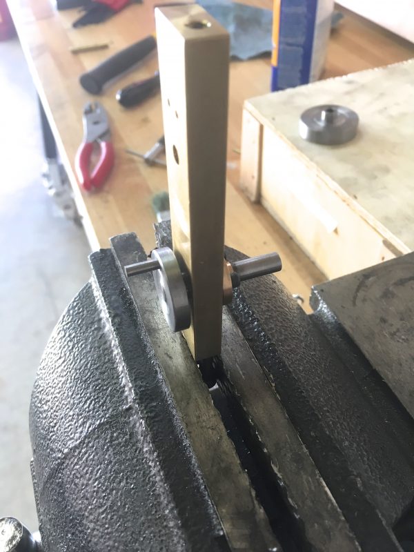
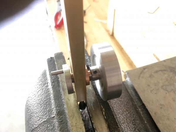
Now we can do our fit-up. The whole assembly should spin freely a couple of times if you give the flywheel a twirl. The cylinder head is not installed, thus we have no compression, so there should be nothing impeding movement. Odds are something is binding though, because physics is hard and the real world laughs at 3D models. It can be difficult to figure what is binding though, because we have a lot of moving parts here. Let’s look at all the places you should check. Much like debugging software or electronics, you want to test moving part relationships in isolation first. Make sure the piston moves smoothly in the cylinder by itself, to eliminate that variable, for example.
Once everything is running smoothly, we can install the cylinder head.
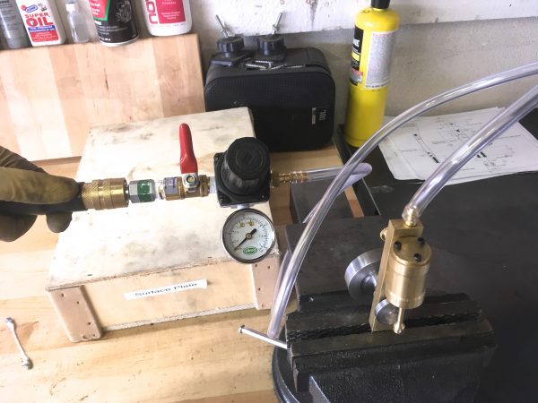
We’re almost ready to run this little guy! We need a system to deliver air at an appropriate pressure. Garage air compressors generally don’t go much lower than 20-30 psi, but we only need 5-10 here. A low-pressure regulator and gauge are needed. The regulator is easy to find, but a low-pressure gauge is trickier. I’m using a tire-pressure gauge intended for garden tractors and other small soft-tired things. I found it at an auto parts store.
Does it run?
Huzzah! It may need a little spin to get going, since this isn’t a self-starting engine design. If it won’t run, make sure you’re spinning it in the correct direction, and when in doubt turn up the pressure. Many small flaws in the craftsmanship can be compensated for with more pressure. As the engine runs-in, it will get more efficient and require less pressure as well. Ideally, an engine like this shouldn’t need more than about 5psi, but if it runs on 10psi, that’s nothing to be ashamed of.
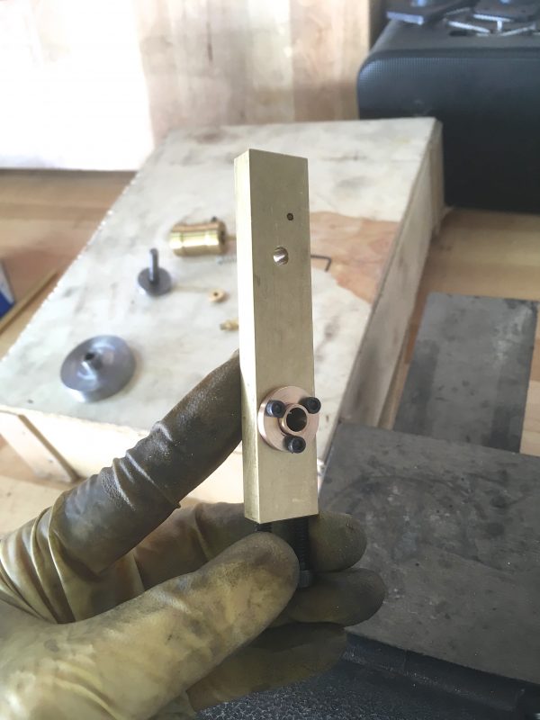
Speaking of shame, a final exercise that I thought would be fun is to compare this engine to the first version of it that I made. I feel like I made more mistakes on the second one, but I honestly don’t know which will run better. In order to be all sciencey about it, I went back to the lathe and whipped up a little tee pipe for my air system. I want to supply the same pressure to both engines and compare how they run in real time.
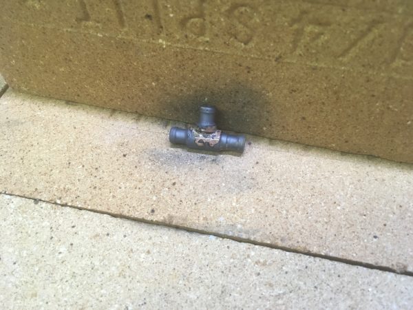
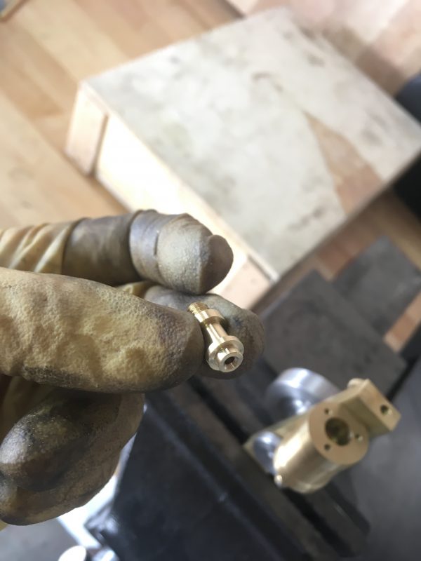
The final step in making a fitting like that is an optional one. After the silver-soldering is done, you then need to run the drill through it again to clear all the clumsy excess solder you used that plugged the passage. Then, break the drill bit in the process, and then also break a larger drill bit that you use to try and free the broken chunk of the first one. Now that you have two pieces of hardened tool steel blocking the passages in the tee, the part is thoroughly ruined and you can finish up by making the whole thing a second time. Again, I must stress those final steps are all optional. I opted to do them, but you should do what works best for you.
Okay, now that we can supply equal parts of Science Air™ to both engines, it’s moment of truth time. Let’s fire ’em up!
The results are quite interesting indeed! The newer engine (with the black flywheel) starts a whole lot easier. However, the older engine runs on much lower pressure. As I turn down the pressure, the new engine dies at about 7 psi, despite my attempts to give it a second chance. The older engine, amazingly, happily puffs away all the way down to 3 psi. The reason for the difference doesn’t show on video, but is clear in person- the piston fitment on the new engine is looser. You can feel leakage around it, which you cannot on the older engine. I got a better fit the first time around, despite having zero experience at the time. It just goes to show that learning is a non-linear process. The looser fitting engine starts much easier, because it has less resistance, but requires more pressure to run because it’s sealing poorly.
Well, that wraps up this engine project. We have more steam related things in the pipeline, as well as more electronics and other classic Blondihacks-style stuff coming. Don’t touch that dial! Thanks as always to my Patreon patrons, who make this blog possible.
Nice work! …and, as always, your sense of humor is spot-on. Especially at the end there — when you described what you did to that poor Tee fitting, I did indeed literally laugh out loud.
Well done 🙂
Too cool!
Nicely done. I wonder if a larger flywheel on the looser engine would make a difference in how low the pressure can be before it stops. Maybe you could switch them and test. 😉
That’s an interesting question! I suspect the answer is “no”. The flywheel transfers power from one part of the cycle to another. However, the leaking piston is costing power at the source. The flywheel is making loans from a crappy bank account.
The lighter flywheel probably does contribute to the much easier starting of the leaky engine, though! Less inertia to overcome.
By the way… I’ve liked this design for a compressed-gas motor as long as I’ve known of it…
http://www.animatedengines.com/co2.html
Oh gosh, that is an exceptionally clever design. I’ve never seen that before. Thanks for sharing! I may just have to build that one day.
Remember those “Air Hogs” plane and helicopter toys from the late 90s? the ones with a compressed air motor in ’em?
Yeah. That’s the mechanism. I imagine that adapting a two-stroke motor would not be a significant challenge for someone with experience in working metal, such as yourself… but I could be wrong. I work cardboard and thin, inexpensive plastic 😉
Oh cool! I didn’t know that’s how Air Hogs worked. I will definitely be building an engine around this mechanism. It’s too clever not to. There seems to be an interesting tradeoff though- the higher the pressure, the harder it is to open the intake valve, and thus the less efficient the engine gets. There’s probably a moderate-pressure sweet spot.
I don’t wonder if a spring somewhere in that valve would counteract the pressure problem… but I’m nowhere near as mechanically inclined as you are, so that may be a red herring.
At any rate, I look forward to what you come up with…