Wherein we may solve this problem once and for all.
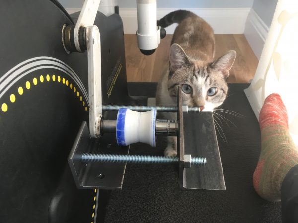
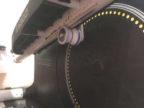
My elliptical machine has been a regular feature here, starting with upgrading the power source in the very early days of this blog. It’s been revisited many times since to have the critical foot pedal rollers addressed, replace broken feet, repair cracks in the base, and some other minor fixes that I haven’t bothered to blog about. Those foot pedal rollers have been a chronic trouble spot, however. My last repair with the rollerblade wheels held up surprisingly well, I must say. I got four years out of that arrangement. Then, the other day, I noticed this:

It looked like that roller was shedding wheel rubber somewhere, so I pulled the retaining bolt to have a look. I did not expect what I found.
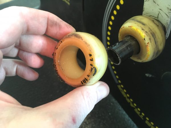
This damage happened all of sudden over the course of a week. My guess is either the center bushing seized (causing the wheel to start rubbing) or the wheels overheated, weakening the material until sudden failure. I had noticed the friction in the foot pedals increasing over time (despite regular greasing), and the rollers were always very hot after using the machine for 30 minutes. Honestly, I’m amazed they lasted four years.
Well, a lot has changed in the Blondihacks shop in those four years. I now have the ability to do a proper fix for this, because there’s a machine shop in the building now. Let’s do what we wish we could have done four years ago- make proper new rollers from scratch. Once you own a machine shop, most repair jobs go from “Gee, I wonder if I can find that part on McMaster-Carr” to “Oh, I can make that part”. It’s very liberating.
I thought a lot about what to make these rollers from. One option is brass or bronze, which would run nicely against the steel foot pedal pipe. However, I was concerned this would be noisy. The factory rollers were some kind of fiberglass-reinforced nylon, but I can’t machine that. I decided to try Delrin (aka acetal), which is a durable machinable plastic. It’s commonly used as bearing material in heavy machinery, so it should stand up to this application. I decided to Do This Right and add proper bearings to my rollers, rather than the various bushing arrangements used in the past (including on the factory ones).
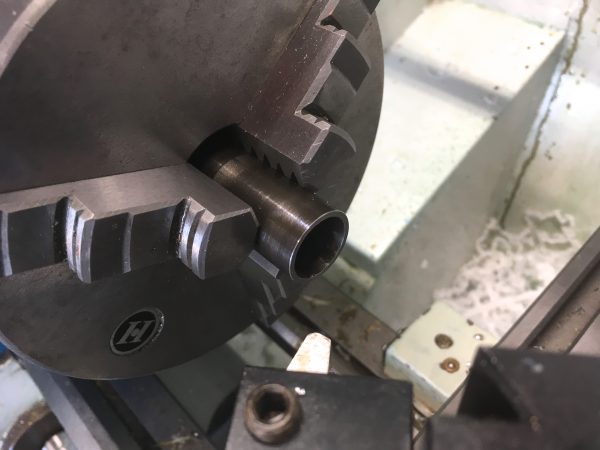
McMaster-Carr also sells Delrin by the foot, which is extremely convenient for small projects like this. All parts in hand, I set out to turn these rollers on the lathe.
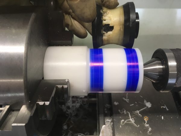
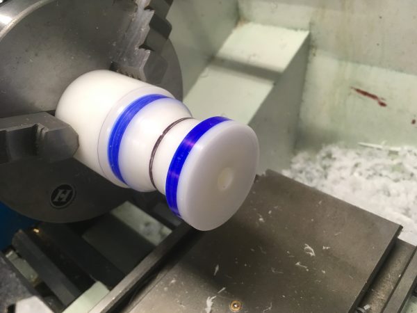
At this point, I needed to turn the large U-channel in the middle. This is what the foot-pedal pipe rides in, and truth be told the dimensions aren’t super critical. The main thing is that the center (smallest diameter) is the right size, and that the overall shape constrains the pipe’s motion sufficiently.
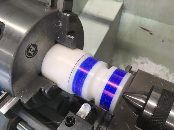
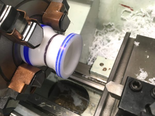
With the center dimension established, I cut the curves on either side to meet that by hand. To make sure I didn’t cut deeper than this established dimension, I marked it with sharpie so I could tell if I touched that area. The same round-nosed tool was used for the free-form sections, and I operated the lathe hand-wheels by eye and feel to get the curve.
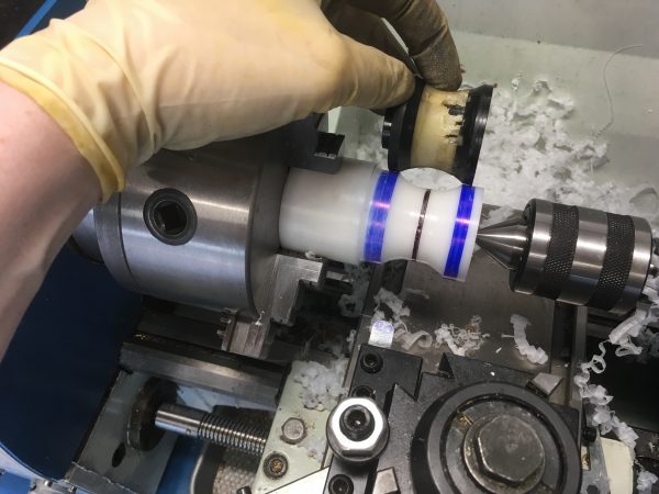
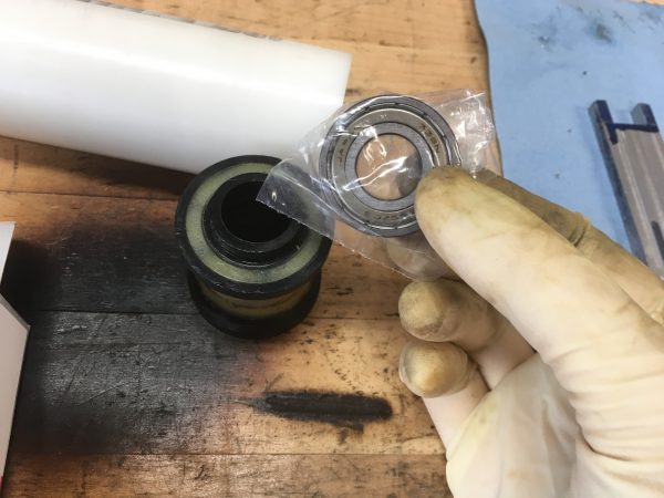
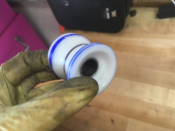
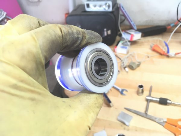
With the shape of the roller established, the next task was to fit the bearings. The idea is to have the rollers fixed to the bearings, and the bearings fixed on the shaft. The center of the roller will have enough clearance that it isn’t rubbing on the shaft. The bearings are taking all the load and supplying the only friction in the system.
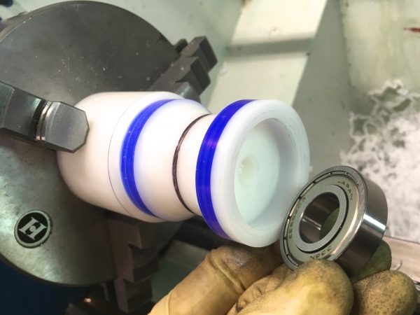
You might ask at this point how those bearings are secured in the rollers. They are a press fit. I honestly wasn’t sure if you can reliably press-fit bearings into Delrin. The internet seems to disagree strongly on this. You’ll find equal-sized groups of angry machinists declaring “I’ve done this every day for two hundred years and it’s fine” and “Of course you can’t do that because duh physics”. This is often the case with machining. Like any complex subject, there is plenty of room for reasonable people with different experiences to disagree. I kinda needed this to work though, because I didn’t have a better way to do it. There was some consensus that bearings will hold in Delrin if the interference is aggressive and the system won’t see heat. The first criteria is because Delrin is quite stretchy, so it’ll take an aggressive press and contract back down again. The second criteria is because Delrin expands a lot under heat, so the bearing would tend to loosen if things got too warm. An aggressive interference fit also helps with that, because it gives the Delrin more room to expand without losing grip on the bearing. The consensus seems to be that a 5-6 thou interference will result in a strong enough press fit for an application like this. We’re really not asking very much of the Delrin here. There’s about 80lbs (you heard me) of human on each one, the rollers turn at low speed, and they don’t have to run for more than 30 minutes at a time. Industrial conveyors and other systems where Delrin is load-bearing take much much more abuse than this.
Confident that this plan was going to work, I pressed on (oh the puns, they burn).
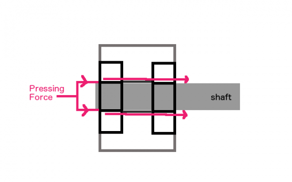
When doing press-fit bearings like this, you have to consider the physics of installation. The pressing forces must never go across the bearing, only straight through one of the races. For pressing the bearings in to the rollers, that’s easy- we press on the outer race. However, think ahead to pressing this on to the shaft of the cardio machine. There will be two bearings in each roller, and we need to press on the inner race of both bearings. That means we need a way to transfer the pressing force from the inner race of the outer bearing to the inner race of the inner bearing. Otherwise we’re pressing on the inner race of one bearing, but the forces are going across that bearing, into the roller, and across the other bearing. A diagram will help:
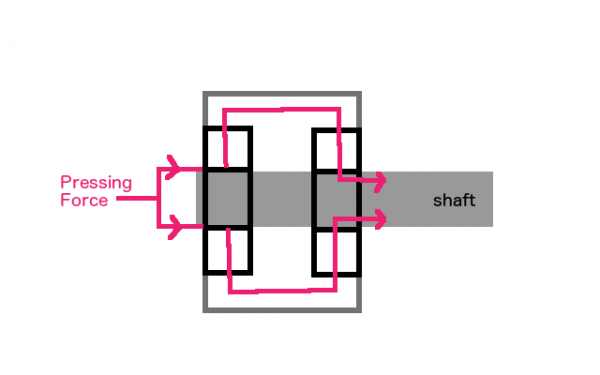
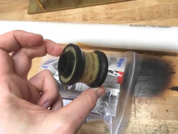
The solution is to add a bushing down the middle to transfer the forces between bearings. This bushing can be a loose fit on the shaft- it isn’t supporting any load and doesn’t move relative to anything in the system. It’s only there for installation.
Conveniently, my previous attempts to make rollers for this machine involved an inner bushing that will be perfect to make my bearing bushing out of. Previously, this tubing was itself the bearing, relying on heavy grease to run smoothly. This was an okay solution, but not very efficient.
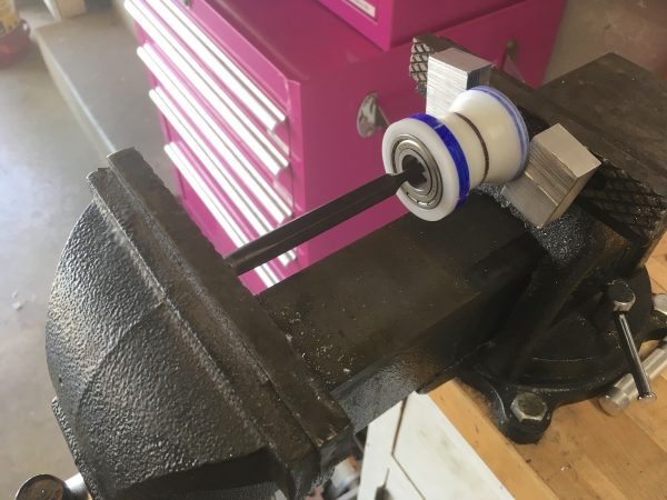
Now it’s time to press the bearings into the rollers. The Blondihacks shop is still missing an arbor press (something I very much need), so it’s time to abuse the vise again.
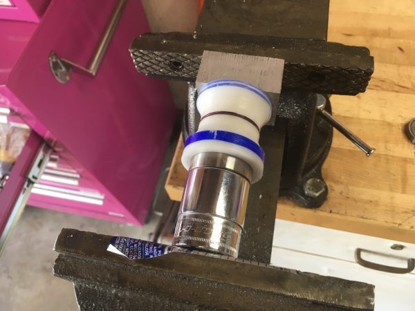
The bearings pressed in very well, and I was pleased with myself, until I looked on the workbench and saw… the bushing that is supposed to go inside. Several minutes of adult themes and situations followed, language-wise. Then I needed to figure out a way to remove one of the bearings without destroying all this effort.
Whenever I order parts, I always order 20-200% more than I think I’ll need. For something like bearings, which are generally needed in pairs, I’ll order an extra couple of pairs. If the project goes well, I have them for a future project. If it goes less well, I have the spares to press on (oh the puns, they still burn).
Via the magic of television, I instantly made another one. Actually I used the cardio machine with just one of these Delrin rollers for about a month, to make sure it was going to work. Then I made the second one.
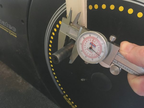
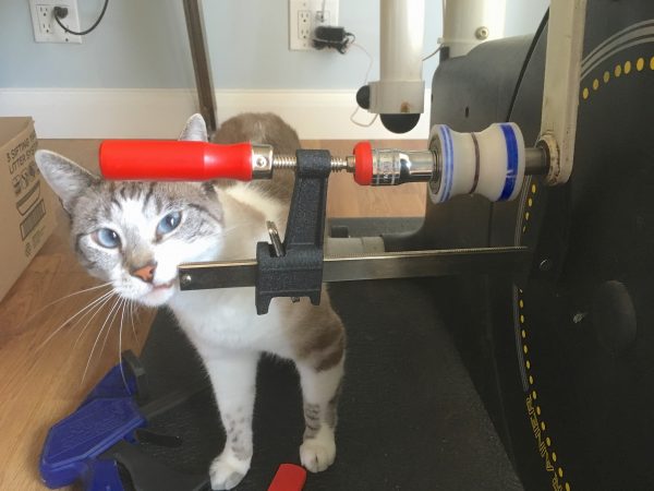
The next challenge was how to install these on the machine. I knew from careful measurements earlier that these bearings should be a perfect one-thou press fit on the shafts of the machine. However, the shafts are welded to the cranks on the machine, so there was no easy way to get them to the bench for pressing. I was going to need a field-expedient bearing press. Luckily, growing up around farm machinery and low budget race cars, I have plenty of experience pressing bearings into things while lying in mud in the dark. At least this would be indoors!
Since there was room for a clamp, that’s the first thing I tried. A good clamp can exert a pretty tremendous amount of force, assuming there is room to get that force applied perfectly straight. There was just enough room for an F-clamp here, so I tried that first.
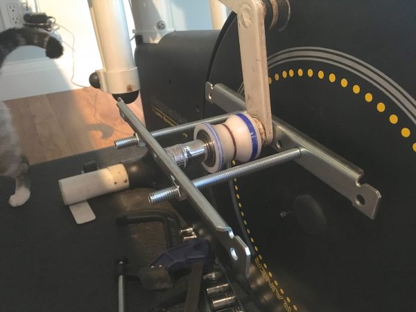
Over on the right hand side, it was a different story. That shaft did not have the taper. For whatever reason, it was in better shape, and by extension, it was a lot more difficult to press the roller in place. Both previous methods were inadequate, so I stepped up my game.
I really hope these rollers work out (LOL puns) because I honestly don’t know how on earth I’ll remove them if the need arises. There isn’t room to get a puller behind them, so I suppose I’ll have to remove the crank arm. That involves dismantling the machine substantially, so let’s hope it doesn’t come to that.
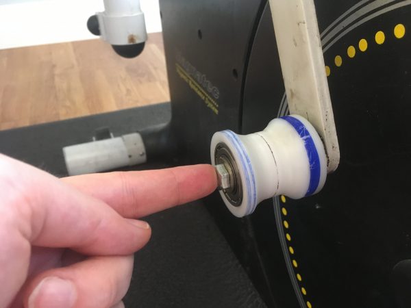
More importantly though, these new rollers work amazingly well. They are so smooth and low-friction that I’ve had to go up a notch on the machine’s resistance setting. I didn’t realize how much “bonus” workout I was getting from the various clunky high-friction roller replacements I had tried previously. The real acid test, however, is temperature. All of my previous roller setups, including the factory one, had the amusing property that the roller mounting bolt would be too hot to touch after 30 mins of use. If that’s not a dead giveaway of high friction (and thus long term doom), I don’t know what is. How does this new roller do in the finger test?
Once again, I easily spent more time and money on this repair than the machine is worth, but it feels really good to keep something running that is, in every other respect, in perfect health. Aside from occasional stress fractures in the frame, these rollers are the only thing that seem to be keeping this machine from being immortal. Let’s see if I can get it to outlive me, just for giggles. What I’m saying is, I refuse to let it die. –ahem- I’m fine.
You should consider setting up some sort of foundation / cult / religion to keep this thing functioning far into the deep future, Clock of the Long Now style.
10,000 years should be a good baseline? I fully expect it to be illuminated and gilded by monks within the first millennium.
Haha, totally. Children will sing songs about it. Anthropologists will conclude every part of it was ceremonial in some way.
Dear aunt Quinn, you look to gracile for a 80lbs-fold woman. I expect those rollers to be stressed with around 40 (50 at the worst) pound-forces each. No wonder the previous ones have been successfully holding out four years.
Love,
Ziggy
More realistically, 80 lb force on each side seem low. On the internet I found a quote that “A walking human will exert more than double his standing pressure” implying the cardio machine will feel more than your body weight on each peddle to do as much good as just walking, so even more with the resistance turned up.
Quinn,
As always it’s great to read about your work, thanks!
This reminds me of some of the stuff a machinist friend did with his vintage Datsun. Needle bearings on the distributor shaft … why not? Makes it better and lasts longer. If you love it and you love doing it, no explanation is necessary.
Thanks for the inspiration.
– Crawford
This is awesome, and getting the bearings started on the untapered side is, I’m pretty sure, a bigger project than you let on.
You need an arbor press. I suggest April 26th as an appropriate time to acquire one.