The cost of procrastination.
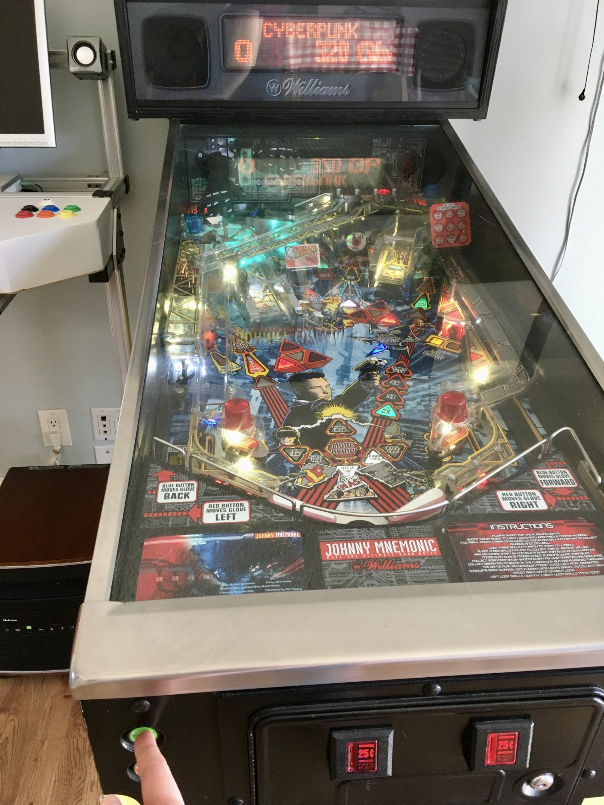
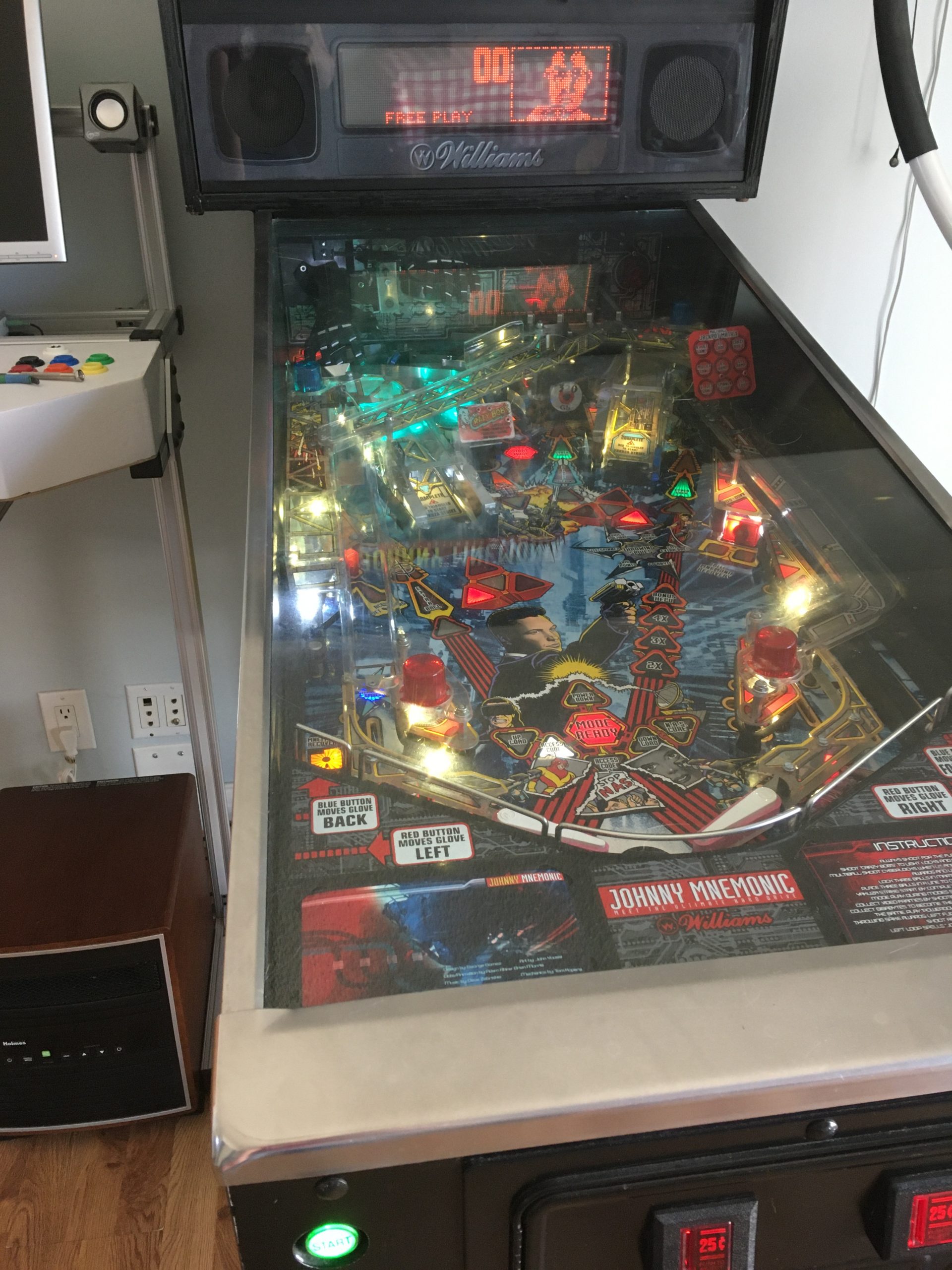
If you’re a regular reader of this blog, one thing you know is that I’ve been having chronic problems with the Start button on my 1995 Williams’ pinball machine, Johnny Mnemonic. If you’re new to the blog you may be shocked to know that (a) I own a pinball machine and (b) that anyone bothered to make a pinball machine about that terrible movie. Yes, it was a terrible movie, but the pinball rendition of it happens to be fantastic, and since I’m the biggest William Gibson nerd that ever lived, the purchase of it was pretty much a no-brainer for me. I’ve owned this monstrosity for several years now, and if you’re considering buying one of these things, I have two pieces of advice for you. First, they are a lot bigger than you think they are. Most of us have only ever seen pinball machines in commercial spaces: bars, arcades, movie theaters, etc. Those are large spaces and large machinery does not look large in them. Large machinery does look very large in your home. In fact, you should check your interior ceiling height to make sure it will even fit. In some lower-ceilinged rooms, it may not. The second piece of advice is that you need to understand that you are not buying a toy, you are buying a hobby. You are buying a perpetual project. Unless you buy a brand new $9000 machine from Stern or the new boutique makers, you’re buying a 30+ year-old electro-mechanical monster that was only meant to last a few years. That means there is constantly something needing fixing on them. They are very much like owning a classic car. You have to enjoy working on them, or you will not enjoy owning them. All that said, the great thing about pinball machines is that they are commercial coin-op machinery. These are not consumer-grade appliances. They are built like gorram tanks, and they are built to be maintained. We’re so accustomed to disposable things these days that it can be easy to forget what something built for maintenance looks like. I talk about this every time I write about Johnny, because it is still one my favorite things about these machines. Every single transistor is meticulously documented, and you can pretty much rebuild the entire machine with a screwdriver and a couple of wrenches. They were built to be maintained by cranky old operators driving around in their vans emptying quarters into a pail and cursing out the teenagers that kicked the coin door again. They are also built assuming teenagers are going to kick the coin doors. They weigh many hundreds of pounds (close to 1000 in some cases) and can take a remarkable amount of abuse. They are also built to fail gracefully. If a particular mechanism ceases to function, the software can route around it and keep the game operational (and earning quarters) until the operator could get to it for repairs. Almost any part on this machine can fail, but the game remains playable. Almost any part. You know what one part is really important? The Start button. Guess which part my game has chronic problems with. Well, you don’t have to guess, because I told you in the first sentence. Literally the first sentence. Keep up Quinn, geez.
If you look back on my Johnny series, you’ll see multiple repairs of the start button circuit. You’ll also notice a theme- I’m constantly doing the minimum that I feel like I can get away with to get the game operational again. That’s not generally my style, but for some reason I keep doing it in this case. I’m about to (probably) do that again, but we’ll get there.
The good news is that I didn’t even have to diagnose anything. I’m normally strongly opposed to starting a repair before doing diagnosis to confirm the problem empirically, and most Johnny posts start with a long section about that. In this case, I have fixed this damn button so many times that I knew exactly what was wrong. To be more precise, I knew exactly what was wrong because deep down I have always known and I have been procrastinating on the correct fix. As you may have read in previous posts in this series, I have traced all the wiring, checked matrix diodes, and all other sources of malfunction between the start button and the CPU board (where the start signal ultimate leads). All are fine. The problem is, and always was, at the connector. Let’s look at why.

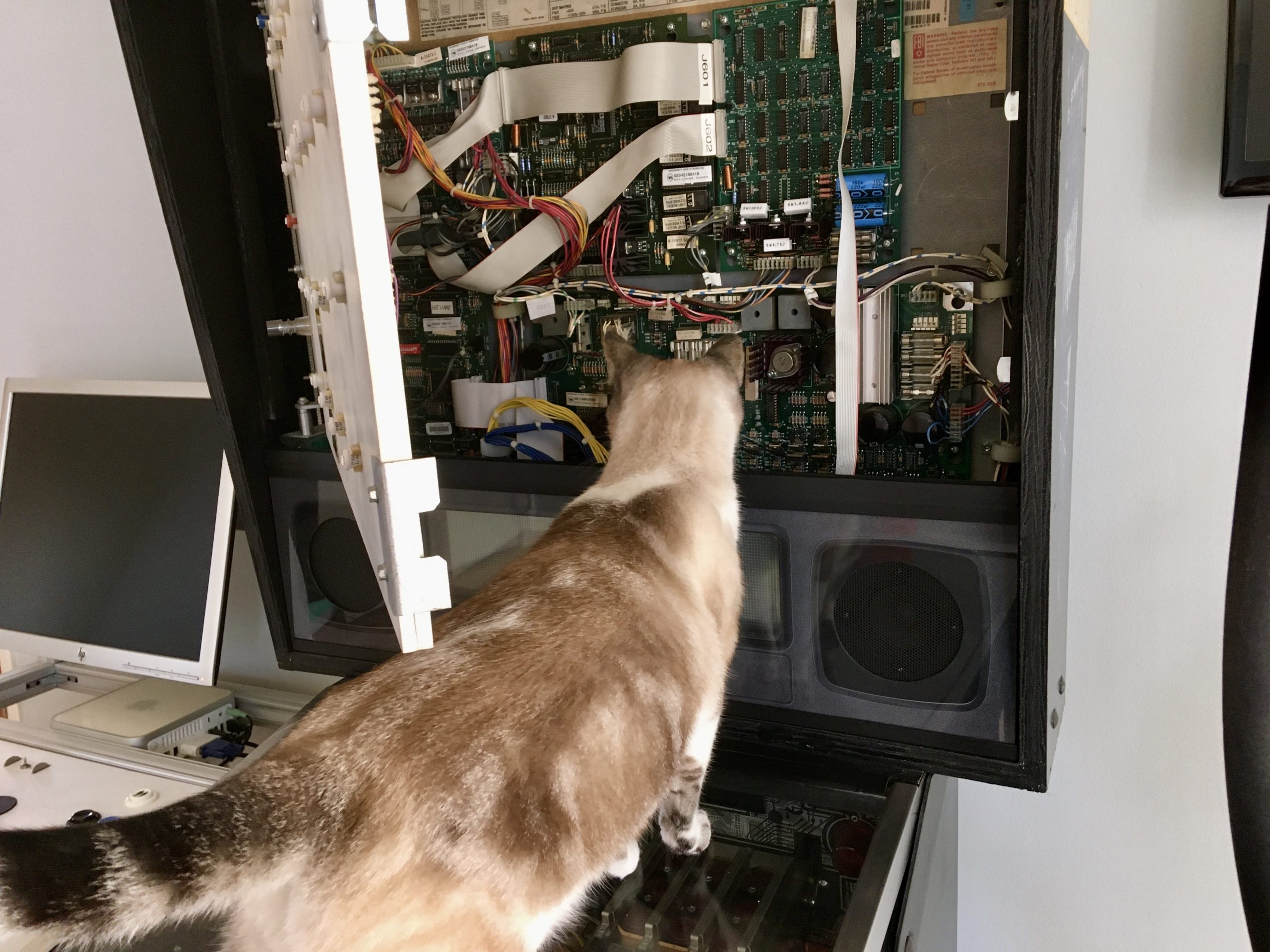
The next step is to call in the supervisor and get her opinion.
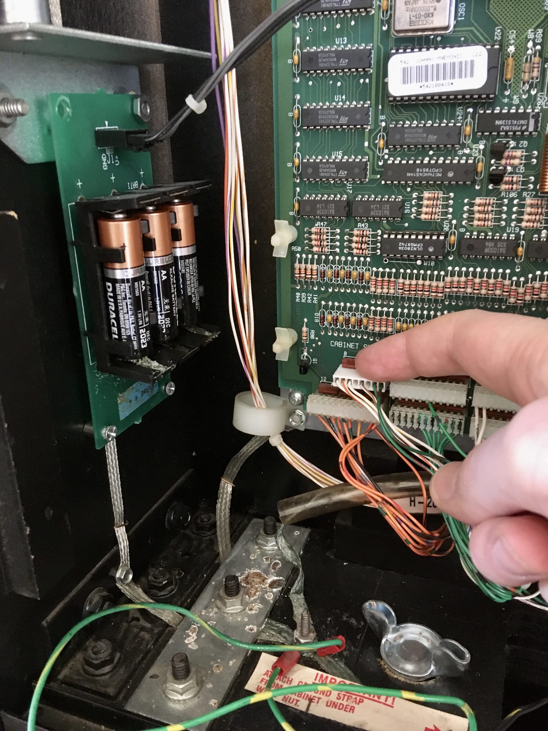
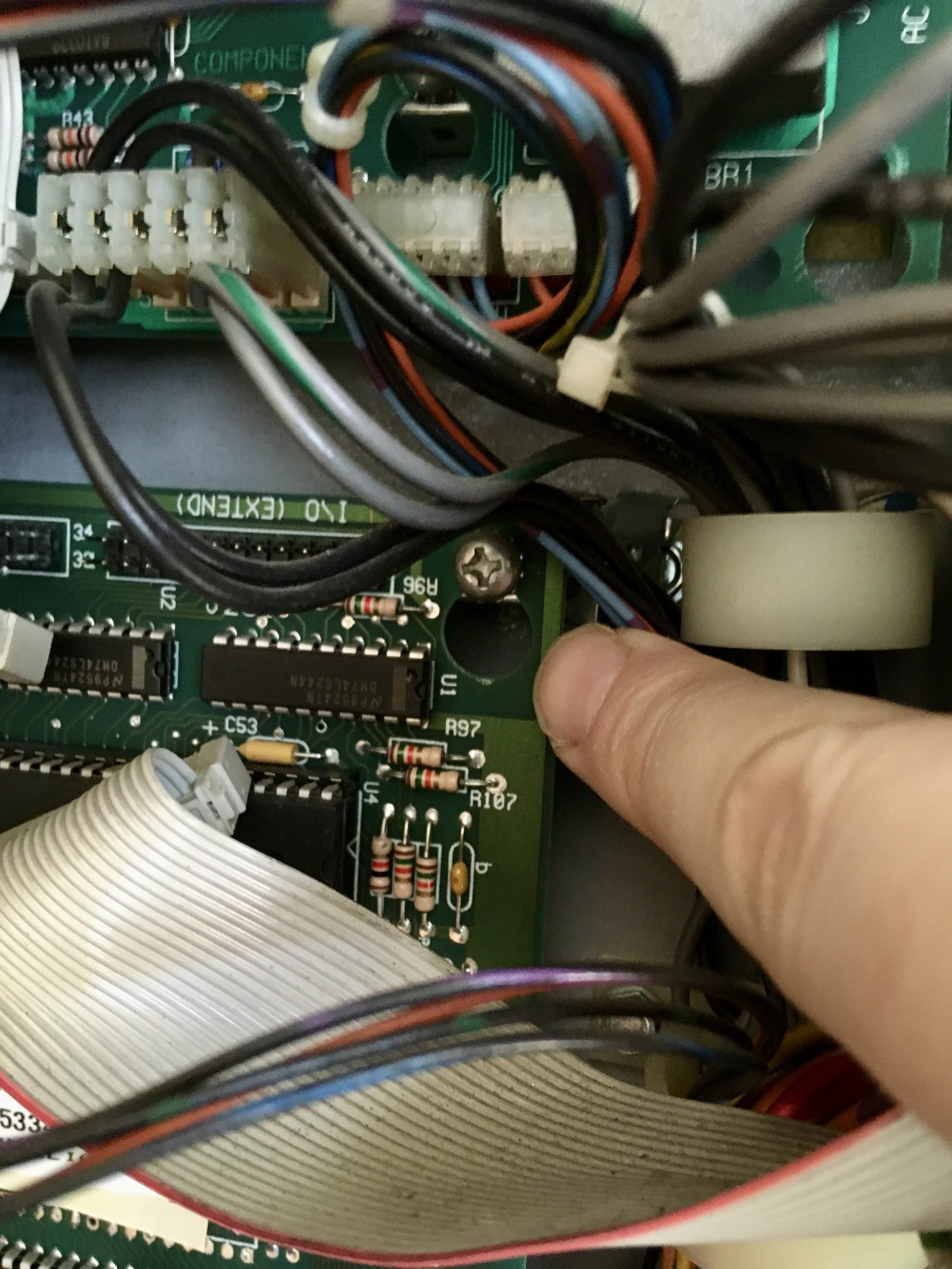
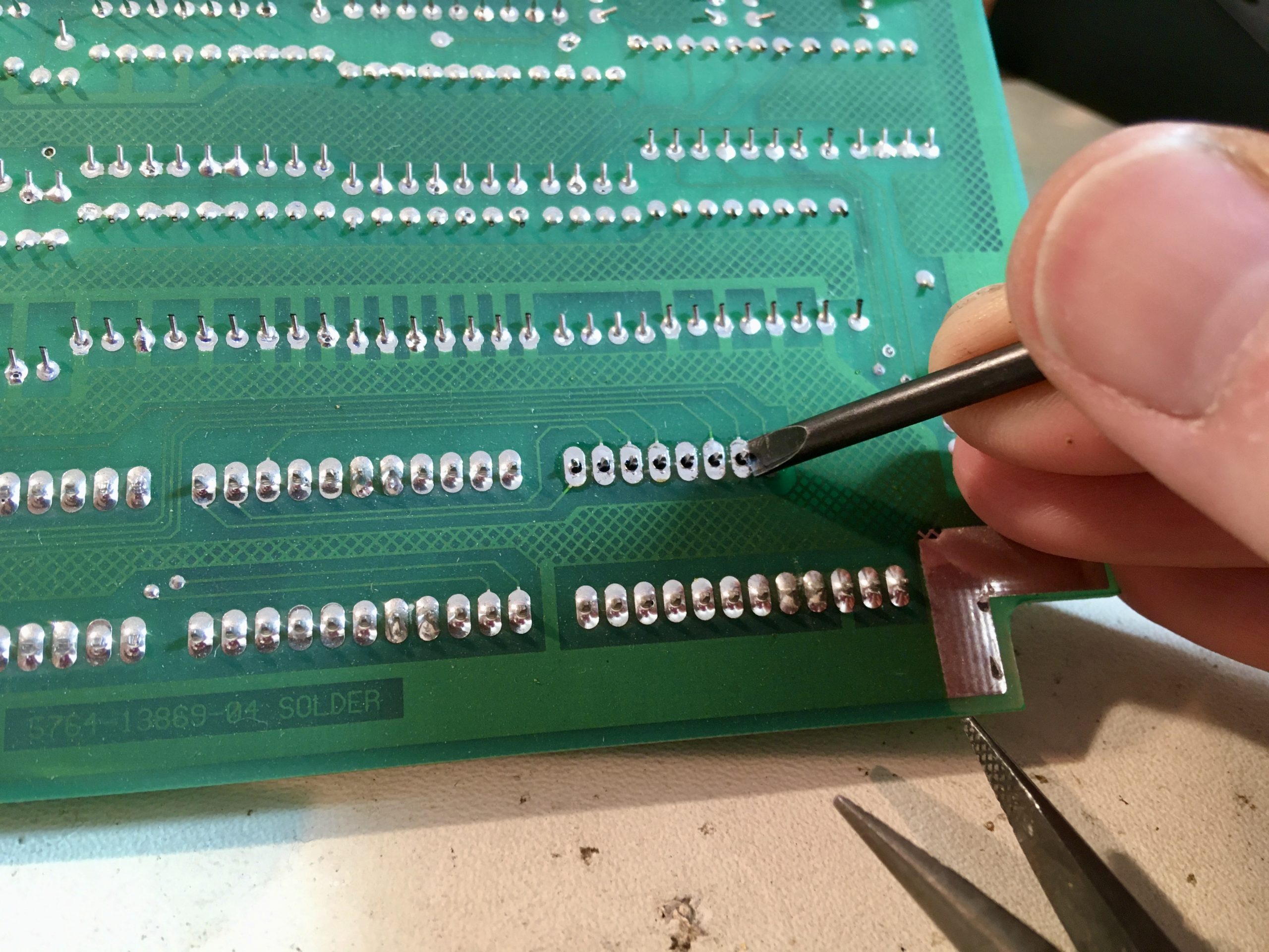
My finger is on the problematic connector. Right off the bat, you can see that it’s a newer style than the others. This is a Molex crimped-pin connector, and the others are all IDCs (insulation displacement connectors). That’s because I replaced this connector previously. The reason this connector is so problematic is also visible in the above photo. See all that nasty staining on the metal bracket in the lower left? That is battery corrosion. In an amazingly poor moment of design, the backup battery for the game is factory mounted double-decker on the CPU board, using plastic standoffs. You can see two them, left of my finger there. That places the batteries directly above connector J212. Guess what batteries do sometimes? They leak. At some point in this machine’s history, batteries have leaked alkaline goo on to that connector, causing corrosion and the subsequent unreliability that I have been living with ever since. When I got the machine, everything looked okay and things were working. The batteries in it at the time were in good shape. Nevertheless, the first thing I did was relocate the battery pack to the side, as you can see in the above photo. That way, if they leak, they can’t hurt anything. I also replace them annually, but in case I ever forget, I’m protected.
It’s maddening that the batteries were not only factory-mounted in a place where they can cause damage, but they are literally mounted over the one connector that paralyzes the game if it becomes unreliable. Amazing. In any case, a couple of years ago I had replaced that connector, because the corrosion was apparent on it. That made the start button reliable again for a couple of years. Recently, it has been acting up again, but I have been able to keep it working by periodically cleaning the pins on that connector. The thing about battery corrosion though, is that it’s like circuit board cancer. It gets into solder joints and on traces, and it will slowly spread. It can be virtually impossible to get rid of once it gets into certain places. In some extreme cases, I have seen retro computing enthusiasts cut away sections of circuitboard and stitch-in new pieces to get rid of corroded areas. In a multi-layer board, if the corrosion gets into the inner traces, this may be the only option. If you have any old electronics you care about, do me a favor and remove the dang batteries. More than a few beautiful old computers, arcade games, and pinball machines have been ruined by this.
In my case, since the connector was new and the problem was worsening again, I knew it was time to look at the male side of the connector, on the CPU board itself. It’s a bit of a job, which is why I have been procrastinating on digging into it. I could procrastinate no longer, because my old tricks of cleaning pins and reseating that connector were no longer working. Johnny was quite dead this time.
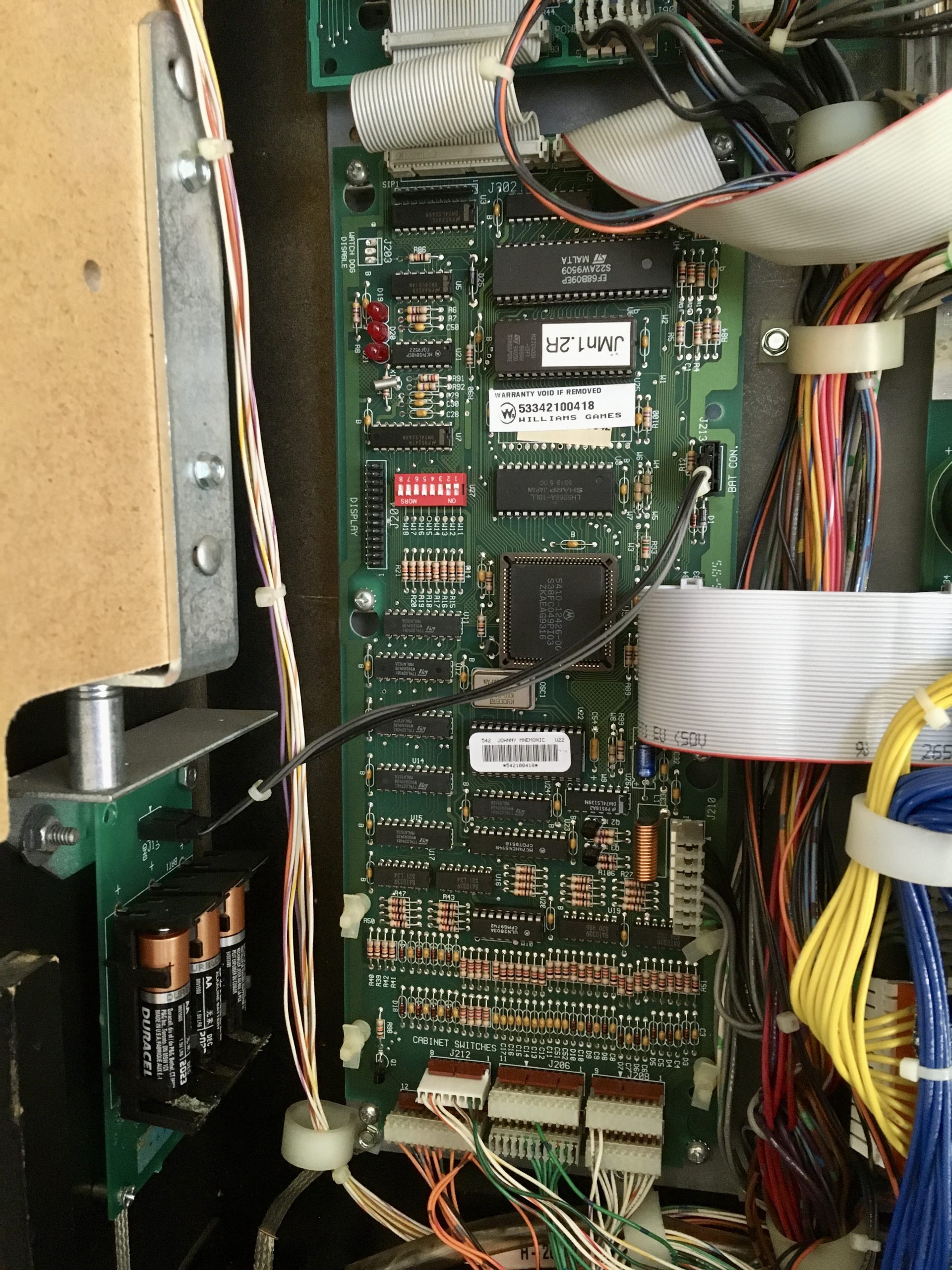

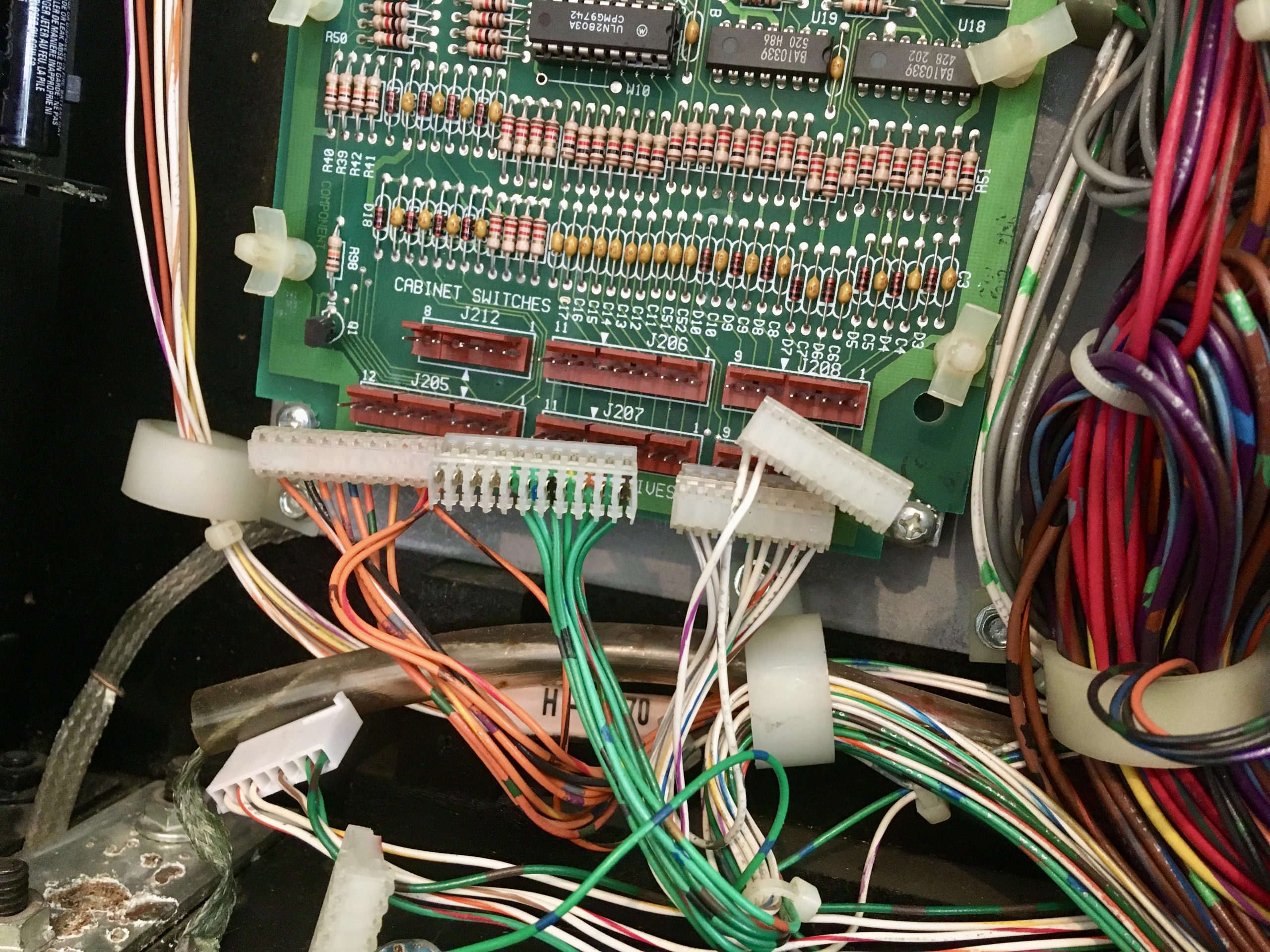
The first job is to get that board out of there. There are a lot of connections on it that need to be carefully removed. Most of them have probably not moved since they were installed 25 years ago, so they may be quite stuck. The easiest way to remove them is to grab the wiring and yank really hard. Kidding! Kidding! Don’t do that, of course. Some care with thin bladed screwdrivers, picks, and gripping the connector’s body with small pliers is sufficient to ease them all off. You have to be mindful not to bend pins, so you have to work them side to side carefully such that they come straight off. If you bend pins on the connectors, you can straighten them again…. usually. If the metal is old and brittle, or has been flexed before, perhaps this is the time it snaps. You pays your money and you takes your chances.
There was a day when I would have meticulously labeled all those harnesses before removing anything. Experience has taught me that, when removing a single board like this, that really isn’t necessary. Those harnesses have been sitting in those positions for so long that they hardly even move when you disconnect them. It’s really easy to see where they all go back on. Even orientation is obvious because of the “set” that the wiring takes, but if a connector isn’t keyed, then it doesn’t hurt to mark one end of it. Most of them are keyed, though. Again, the machine is designed for maintenance.
Speaking of designing for maintenance, note that the PCB is held in place by screws, but they are key-holed, not just simple through-holes. This means you can loosen the screws and simply slide the board up to remove it. Why is that a big deal? They are mounted vertically in the back box of the machine, and below them is a gaping hole into the huge underbelly of the machine (itself filled with high voltage stuff). Dropping a screw in this situation would be supremely annoying at best, and fatal to the machine at worst. The simple design choice of key-holing the mounting spots removes all those issues in one swoop. It makes removing and reinstalling the boards quick, easy, and low risk. See? Design for maintenance. It’s the little things.

Okay, let’s get this board over to the electronics bench and take a look.

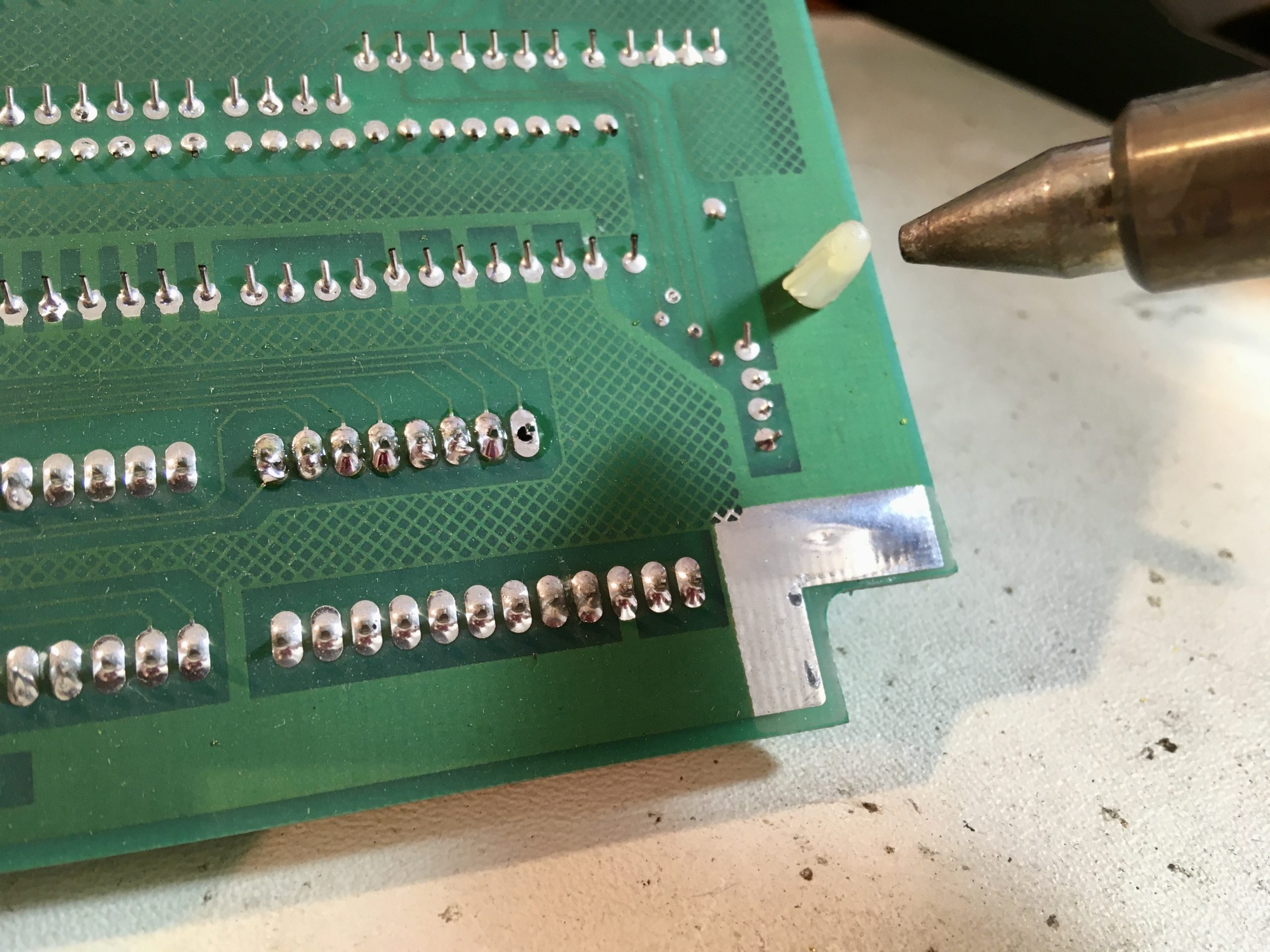
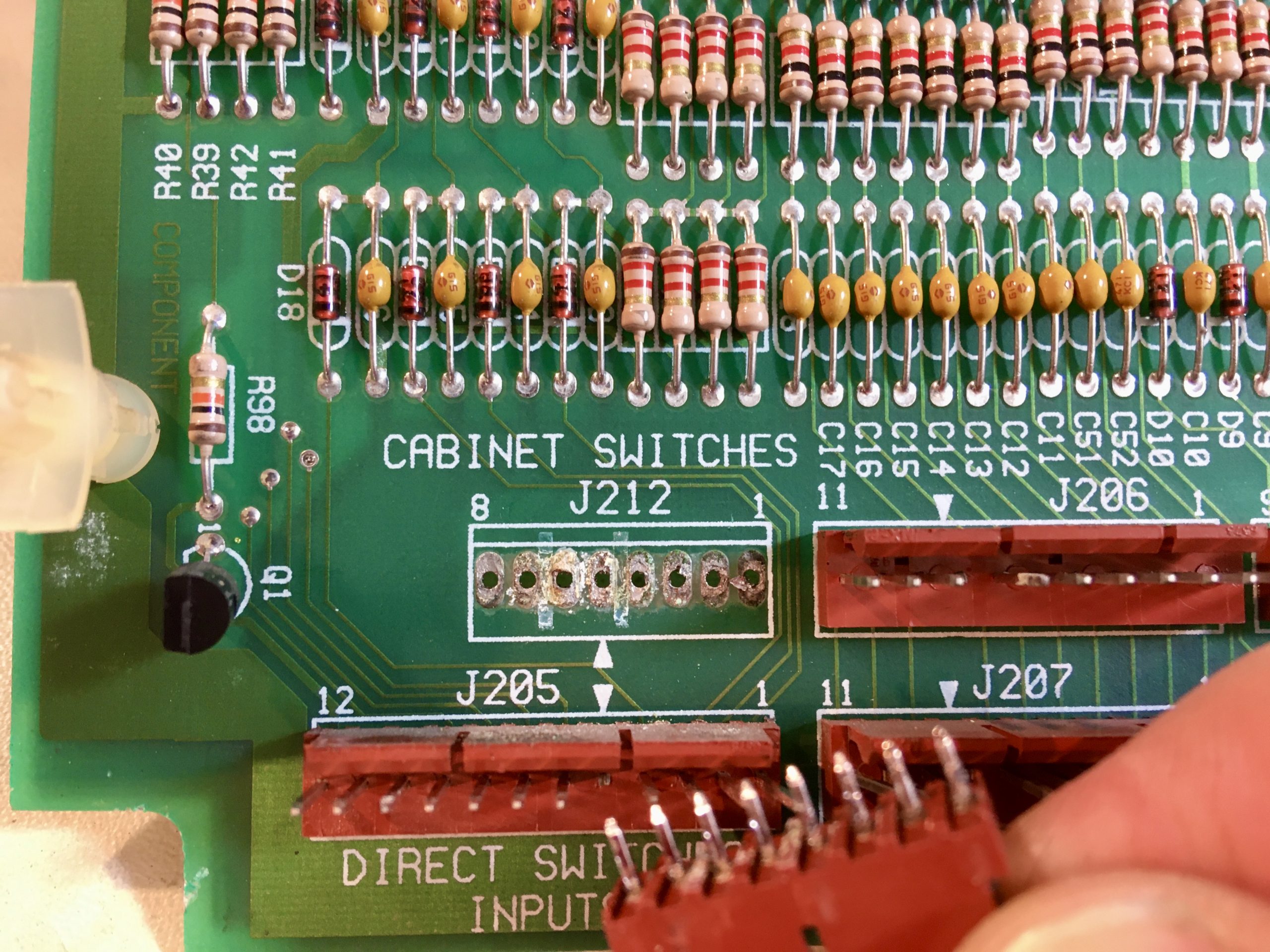
The top is about what I expected. Some corrosion on those pins, but debatably not enough to interfere with function. Let’s take a look underneath.

The underside of J212 actually looks fine. The joints all look okay and no corrosion is visible. There’s another area below it (in blue) that is showing some pretty lousy solder joints though. These look factory, and frankly there’s a whole bunch of these connector pins where the solder is a little light. As you probably know, a pin soldered to a pad should have a nice fillet of solder around it, like a little volcano. A whole bunch of these are flat- there’s barely solder bridging the pin to the pad. I don’t know if these were wave-soldered or done by hand. Knowing a bit about pinball factories, especially from back then, “by hand” is a likely answer. They built everything on these machines by hand, and largely still do. Check out online factory tour videos of Stern some time- it’s very much still a by-hand business. But then, look at most Chinese factories- a lot more of our products are still “hand-made” than we think. We don’t think of them as such if they are made on an assembly line by people in other countries, but an iPhone or your microwave or whatever are all still mostly made by hand. Even the circuit boards themselves. Sure, pick-and-place machines and ovens do most of the SMD work, but a lot of it is still drag-soldered by hand, as are all the through-hole components (unless the entire board is through-hole and can be wave-soldered).
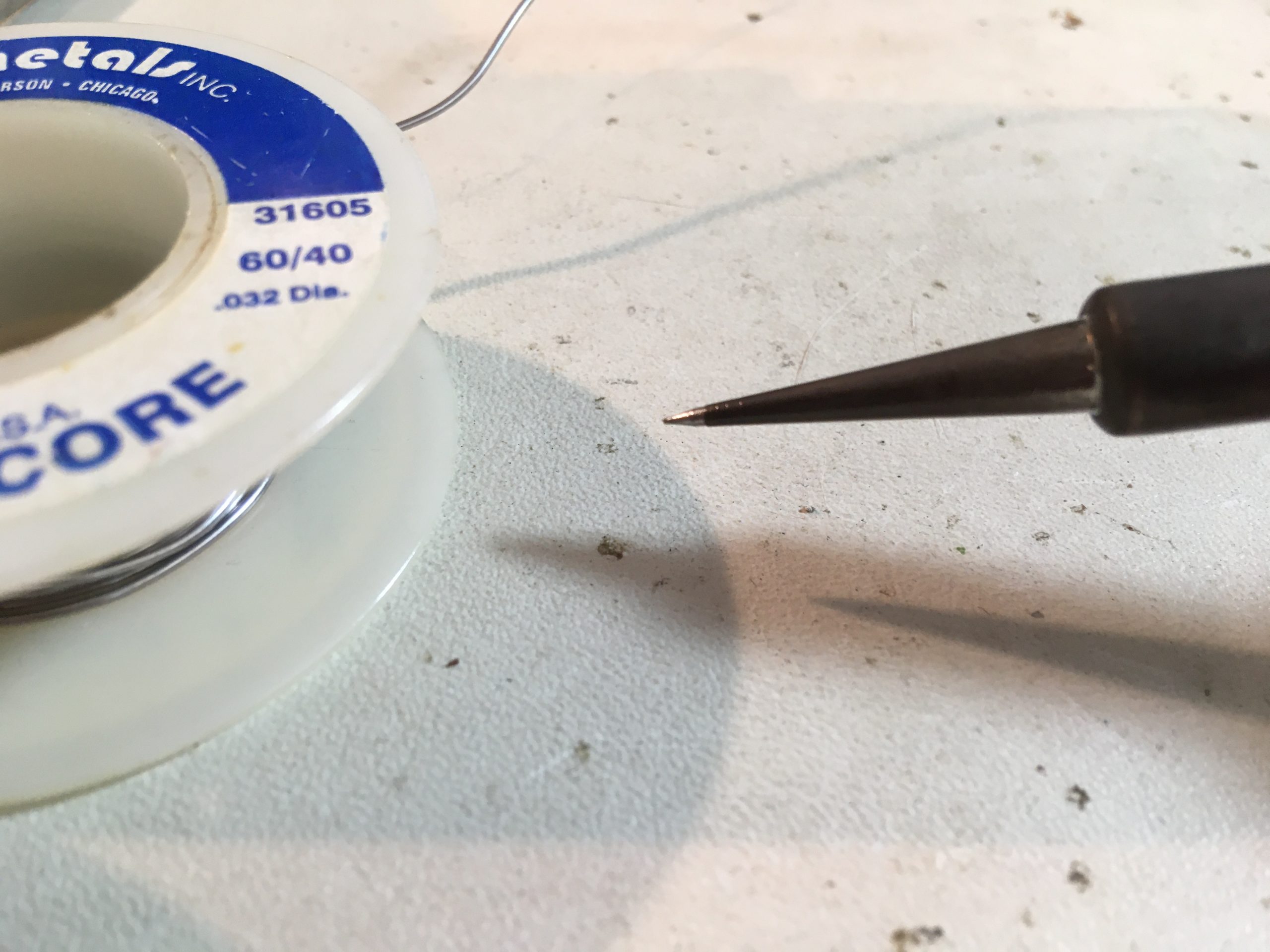
Okay, I got side-tracked there. The solder joints look okay, but I think it’s well worth pulling J212 anyway. Time for some desoldering of very old components, which takes a bit of finesse. The first step, ironically, is to add solder.

Heat management is particularly important when working on vintage boards, because FR4 circuit board material is a lamination of fiberglass, copper, and epoxy. Epoxy is destroyed by heat, and the older it is, the more sensitive it is. If you overheat an area of the board, the epoxy in the substrate lets go and you’ll lift pads off the board or delaminate the area. New boards can take a lot of heat, but on a vintage one you need to get in, do your business, and get out.

Old solder doesn’t liquify or flow well, so adding new fresh solder smooths the rest of the process. We’re about to get out the big gun (sorta literally), and it doesn’t work well on old, brittle solder.
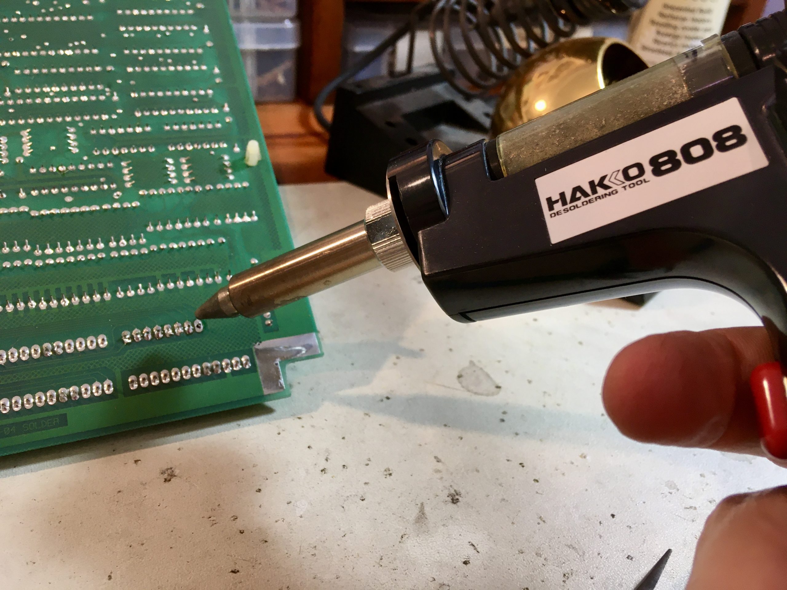
The Hakko is without a shadow of a doubt the most effective and most pleasant way to get solder off a board. There is a bit of technique to it, though. There is a minimum amount of solder required to be there, so it helps to blob on a bunch. It’ll suck up a huge blob with zero effort, but it won’t touch a thin film. You also have to learn to be patient with the vacuum. Give the heat a moment to do its thing. The top rookie move with this tool is to get trigger happy with the vacuum. That makes the situation worse because it sucks up part of the solder, leaving- you guessed it- a thin film. Now you’re stuck. It’ll seem like the tool is ineffective because of this technical error. Put a big blob of solder on there, get the hot end of the gun in place, give it a second or two to really liquify the whole area, then the briefest touch on that trigger and magic happens.
Most of the time, after hitting all pins with the gun, the part will simply fall off the board. If it doesn’t, I’ll give each pin a little wiggle with a screwdriver or pick to make sure it can move. If it doesn’t, there’s a solder film down in the hole somewhere holding it. The urge will be strong to force it at this point, but don’t! You’re likely to tear a pad off the board, and then you’ve quadrupled the challenge of your repair. This is especially true of a 25-year-old board like this. As I said earlier, the epoxy in the FR4 is old and brittle, and the pads can fall off the board if you look at them funny. If you get a pin that won’t wiggle, add more solder back on to it and hit it with the gun again.
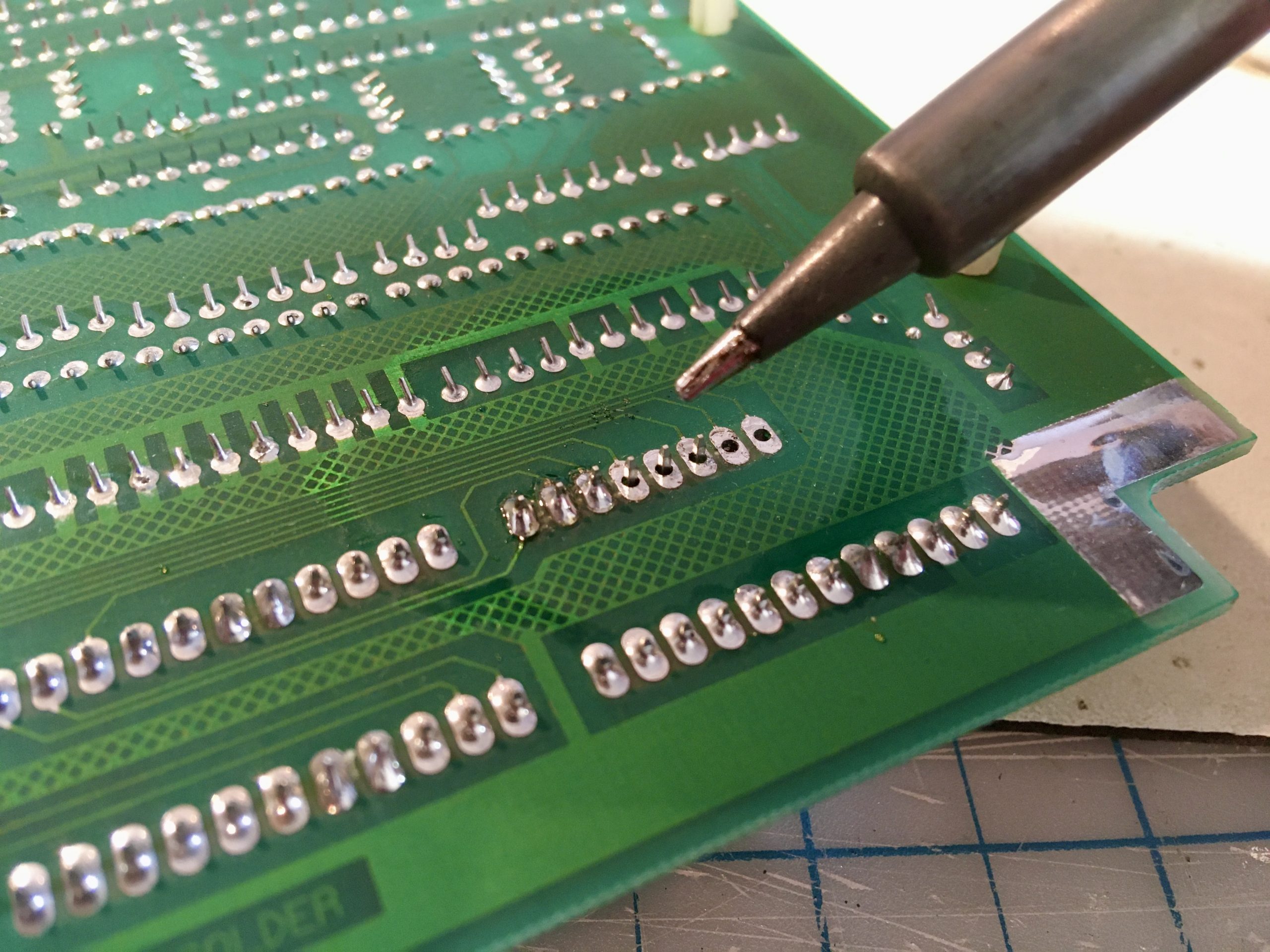
Alright then, with the connector loose, let’s get a look underneath!
I knew there would be corrosion in there, but I wasn’t expecting it to be quite that bad. Well, that’s good news in a way, because we know where to focus our repair efforts. The first step is to neutralize that corrosion. As I said earlier, battery corrosion is like cancer, and you have to stop the reaction or it will continue to eat away at the traces and inner layers of the board. A good tool for this is vinegar. A lot of people refer to this corrosion as “battery acid damage” and you even see people try to neutralize it with baking soda. I guess this is a failure of our education system, because the batteries say right on them: ALKALINE. They are basic. This is base corrosion, not acid. I suppose people think batteries are all acidic because car batteries are, and that’s a big part of peoples’ life experience with batteries? I don’t know how we, as a culture, got the wrong message on this. Anyway, you want an acid for this job, and if you’re not in a hurry, a mild one is nice. Vinegar works, albeit slowly, or something like CLR or Bar Keeper’s Friend work if you’re in a bigger hurry. The latter is oxalic acid and comes in powder form. Mix up a solution and you’re good to go. It’s amazing on calcium build-up on shower doors and such as well (hard water deposits are basic, but too tough for vinegar). I wouldn’t use anything stronger than home cleaning supplies on a circuit board that you care about. You could create all manner of new problems if you get in there with brazer’s pickling acid or sulfuric acid from pool chemicals, or even worse something like hydrochloric or nitric acid (all of which I have lying around because my shop is a wonderland of bad ideas).
By the by, a lot of people put circuit boards in the dishwasher to clean them. Yes, this really is a thing. Pinball and retrocomputing people do it a lot. I have never done it myself, but it appears to be fine. However, if you’re thinking that will clean this corrosion off the pads, you’d be wrong. Why? Because detergents are- you guessed it- basic. Most food is acidic, so if you want a soap to be good at cleaning it away, make it basic. This is also why toothpaste is basic. A little junior high school chemistry gets you a long way in this world. Probably the stuff after junior high too, but I dunno. I stopped listening shortly thereafter. I’m sure it was all great.
After soaking for a few hours, it was time to clean up the mess. The vinegar reacts with the corrosion and leaves a precipitate on the pads (not sure what it is, I ain’t no chemist) that we need to clean off so that solder can once again be used. Anything to be soldered must be clean!

To clean up the pads, I used a combination of scotch-brite, brass wool, and some careful scraping with an X-Acto knife. I do a final cleaning with alcohol and cotton swabs. Once this is done, you can re-tin the pads with fresh solder. I also use a generous amount of liquid flux while retinning the pads, because it has an excellent cleaning action that will get any remaining fine residue off there.
Now I needed to deal with that connector. The pins had a fair amount of corrosion on them, and I was concerned that if I reinstall that connector, the corrosion will simply spread again. I needed to replace it. By a stroke of luck, I had that exact style of connector in my junk pile, except it was two pins too short (of course). However, I had two of them! I hacked one up and made the connector I needed from the pieces.
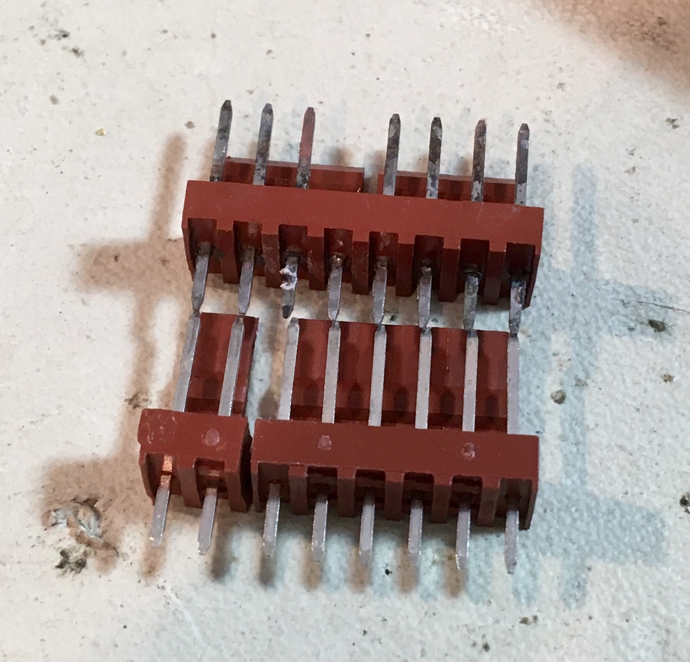
If you’re wondering why there is a pin missing in the original connector, that’s a key. I clipped the same pin on my replacement connector. Now the best part- reassembly!
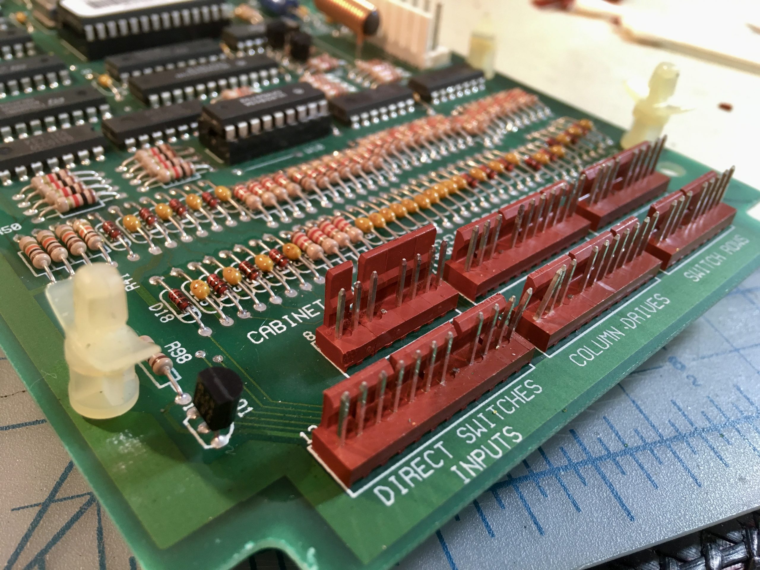
Looking good so far. Time to put it back in Johnny!
Okay, moment of truth time, did I fix it? Time to power up.

You know, I really should have realized what was going to happen when I disconnected the batteries and pulled the CPU board. Of course that would mean I’d lose all the settings. More importantly though, I lost all my high scores. Had I thought about this, I would have left the battery pack connected to the board throughout the repair and it would have likely retained everything. I’ll be honest, I was genuinely a bit sad about this. You see, I had one very special score in there. Modern-era pinball machines like this have something called a Wizard Mode. It is so named because the The Who pinball machine was the first to do it, and it was named for Tommy The Pinball Wizard (of course). A Wizard Mode is like a final “mission” in a video game. After you complete all the tasks on the playfield, you get access to this special mode. It’s how you “solve” the game, basically. Johnny Mnemonic’s Wizard Mode is particularly epic, and is one of the main reasons I love the game. It’s called Power Down. When you start this mode, the game actually physically starts powering itself down in sections. For real. You have to hit certain shots repeatedly to keep the “battery” charged and keep playfield sections from shutting off. If you lose an area, then the pop bumpers go dead, it gets dark so you can’t see what you’re doing in that area, gates that you need get stuck closed, etc. It’s an incredible fourth-wall-busting experience the likes of which is rare in pinball. Why am I telling you all this? Because I have reached and completed Power Down exactly once. It is difficult and I’m frankly not that good at pinball. I was so proud of that score that it was my avatar photo on Facebook (back before it was evil and I was still on it). You can see that score in the first photo in this article. Why? Because I waited for the attract mode to show the score before taking the photo so you would see it. That score was the greatest moment of my pinball playing life. And it’s gone.
It’s okay- I did it once, so I can do it again. It’s a bummer, though.
On a lighter note, the game wouldn’t start yet, because it demanded that I set the clock. Why is that funny? Because I have owned this machine for almost 10 years and I literally had no idea it had a clock in it. I’ve never pulled the batteries before, and it doesn’t show the time in the game anywhere. Why does it have a clock? I suppose because the game has internal financial bookkeeping intended to be used by operators. I suppose it date-stamps that data, I’m not sure. It’s a whole region of the menus I’ve never really ventured into because it’s really dry and when you’re doing that you are not playing pinball. Digging through financial menus on a 4-line screen is a lot less fun than playing pinball, I can tell you. In any case, it won’t boot until you set the clock.

I had no idea how to even set the clock. It was buried waaaay deep in menus that I didn’t know were there.

Now we get to the real moment of truth! I set it to free play (it defaults back to quarter play and I don’t even have coin mechanisms in this machine) and pushed the start button.

Well. That’s disappointing. However, I was still extremely certain that the corrosion on that connector was the problem and I was very confident in my repair. So, I wiggled the connector a bit.
To quote the Buffy The Vampire Slayer musical, “The battle’s done, and we… kind of won?”. The start button now works, and appears to work reliably. However, it didn’t until I jiggled the connector a bit. That’s a trifle worrisome. It may be that there is corrosion inside that connector, picked up from the pins. Ideally, I should repin that connector to be sure. However, remember how I said that the harnesses in these machines are all exactly the right length? That’s no joke. I re-pinned that connector once before, and you lose some wire length every time you do that. There was barely enough wire to do it once. To do it again, I would have to splice all those wires and make a big mess of the harness. Is this more procrastination on my part? Perhaps. Or perhaps you have to draw the line somewhere. I’d already spent the better part of a day on this repair, and maybe the connector is fine. Maybe there was grit or some leftover flux in there. I’m going to leave it be, and if it gives me trouble again, I’ll have plenty of chance to catch it before the corrosion spreads back down into that connector. At least… I hope so.
Dun Dun DUNNNN
Anyways, that replacement Power Down score ain’t gonna earn itself. Gotta go play.
Looks like Johnny got that upgrade.
Snatch back your brain, zombie!
Yes, I’ve seen the movie, and I loved it, even if it was terrible.
What are you doing?
I’m making a long distance phone call.
All these cheesy phrases are etched in my mind forever.
Nice Repair, and the Goramm reference is epic. I do love how well built these machines are. thanks For sharing, I look forward to your next adventure into the mini world of Electronics as the true Tron Warrior that you are. Vic
Quinn, this was fun to read! You are a good writer. And you apparently have some other skills as well. It’s a treat to ride along with you. Thanks for sharing!
Phhwhuuutt? This ain’t machining, Quinn. This is nerding. Are you okay?
Dean
As an old guy that used to fix arcade machines – board level – for a living – I can give you a hint. The buttons they used really want more voltage and current – so corrosion forms on them and they don’t work. (Look up dry contact switches for the details).. In an arcade with buttons getting constantly pressed it isn’t much of a problem – but if it sits.. they can fail – use contact cleaner INSIDE the switch.. but you can’t get the good stuff anymore.
The other things I would look for – as you have – are bad connectors – there was a time when they used the wrong kind of plating back then – they would get fretting corrosion – and if you fiddled with things – it would work – for a while. The ROM sockets also would need some contact cleaner and re-seating the chips. If you were careful – and measured resistance – about an ohm or so – and that was enough to put all sorts of noise on the power bus.
The battery corrosion got fixed with a run through the dishwasher – followed by a rinse in distilled water – then wait for it to dry and spray it down with contact cleaner one last time (yes – sounds weird – but it worked) FR4 was pretty good material by then – compared with the old phenolics it was a dream.
First time I’ve read your blog as a newbie Patreon guy. I enjoyed every word, understood everything too (I ain’t no chemist and I ain’t no leccy (electrician) either) so that must be a tribute to your writing skills and clarity of explanation. Thanks Quinn, love the YT channel.
Hi Quinn, Thank you for such a thorough explanation of the steps needed for repair. I am a newbie when it comes to electronics repair. I learned so many things about older electronics here. I have a 1990 stereo that has some leaking caps that will probably need replacing soon. So, the information on old boards was particularly useful.
I don’t have a solder removal gun. I have just been using solder wick. Would this be a bad idea for use on an older board? Would I risk putting too much heat on the board?
Thanks!
To be honest, I’ve never had great luck with solder wick. It takes a lot of heat and I don’t find it very effective. A low cost alternative to a desoldering gun is a “solder sucker”. It’s a spring loaded device that put near the joint. You heat the joint with the iron, then push a button on the solder sucker and it vacuums the liquid solder away. They work quite well. Search for “solder sucker” and you’ll find them. Hope that helps!
I currently use a very cheap solder sucker. It’s… acceptable.
Having used both, how much better is the Hakko 808? Is it worth the cost?
That’s a good question. I suppose, like most things, it’s down to how much of it you will do. If you’re doing the occasional repair, the solder suckers are fine. For a project like Veronica, though, the gun paid for itself 100 times over. I was rebuilding entire boards, pulling chips on and off, etc, quite a bit. Once you have quick reliable solder removal, you can use soldered boards for prototyping. You stop using breadboards and all the annoyances and unreliabilities that go with them. For Veronica’s VGA video board, I had to develop it with soldered parts on protoboard, because the breadboard couldn’t cope with the 20MHz signals flying around. It was an unreliable mess. For a project like that, the Hakko is a no-brainer. For the occasional job, the sucker is an easy win for $5.
I have never been able to fully clean a pad with a hard-nosed cheap sucker because you just can’t seal it to the board tightly enough and it leaves that thin film Quinn hates so much. Well, I bought an expensive sucker, the SS-02 for $25, and it sure makes a difference; I can clean off even a thin film off a pad with the tight seal that tip makes. There are spare tips sold separately, and since they are the main improvement, you might try retrofitting one onto your cheap sucker before dropping the big bucks.
The first thing that came up on eBay for “SS-02” was a golf club, which seems like an extremely excessive way to remove small amounts of solder.
The solder suckers after that seem neat and better designed though. I’ll give them a try at some point.
Thanks for the tip!
Solder wick is just fine for most purposes. The good stuff has flux, but I always wipe it with a flux pen. Flux pens are even more magical than the 808. Both are invaluable when working on surface mount parts.
Size the solder wick to the job in hand, don’t use force, go slow and if in doubt, add more flux or solder.
Of all of the manual desolder pumps I have used, only one had the right kind of damping so that you didn’t get the hideous recoil that jams your iron into the board and ruins your day.
(I can’t give a part number for the good solder sucker. I bought it in the UK many moons ago.)
For about half of the Hakko price, one could try your luck with the Banggood knock-off:
https://www.banggood.com/S993A-220V-Electric-Solder-Sucker-Desoldering-Gun-Soldering-Iron-p-931626.html
Mine’s worked pretty well for over a year.
Glad to see you back! I was missing your entertaining and informative posts.
Back when I was a high school snot, I would work on weekends in my uncle’s shop fixing pinball machines. He and his partners (who I later found out were mobbed up) had machines installed in just about every dive bar on the north side of Chicago. I was too young to go into the bars, so the machines on which I worked were all brought in from their locations when it was time to swap them out with different machines.
This was well before the introduction of digital electronics to their innards, which meant, of course, it was 100 percent electromechanical. There were cradle relays, contactors, more cradle relays, rotary stepping relays in some cases (which were really cool), and of course, a monster transformer to power the mess. I won’t even mention the miles of wire that hooked up everything.
Back then, as now, connectors caused many of the problems. As Quinn notes, pinball machines are built like tanks, probably strong enough to take a hit from an artillery shell. However, they have a weak link, and that link is in the form of flaky connectors. So many of my repairs had to do with connectors. That was not to say the relays, contactors and solenoids didn’t need attention. Most of that attention was cleaning contacts and solenoid plungers, not actual repair. That stuff hardly ever broke.
The really fun part was cleaning up all the beer, whiskey, etc., that found its way into the machines. ‘Twas not my favorite thing by a long shot.
One of my favorite part names on a pinball machine is the “beer seal”- a piece of weather-stripping under the front edge of the lock bar, designed to keep liquids spilled on the glass from running down into the coin mechs and front panel switches. 😀
Wild guess for the white powder left over after neutralising the battery goo is potassium acetate (apparently the alkaline solution tends to be potassium hydroxide).
I hope this keep Johnny in good health for a long good while. I would also like to say “thanks” for the excellent tee designs (I have one apron tee, and one Sprocket the Riveter).
That’s great! I worked with an awesome artist on those designs, but they’re way less popular than the simple logo shirts. Go figure!
Huh. I would’ve thought they’d be the most popular. I guess a small logo is a bit more discreet[1] than something that’s the bulk of the front (and/or back!). But, they’re not nearly as fun.
[1] I initially wrote “discrete”, but a good tee should be continuous.
Hi Quinn,
Nice work!!
Possibly facing the risk of trying to teach grand mother to suck eggs…
The pins on the connector look nickel plated, make sure that the connectors in the female part are also nickel and not gold plated! If not, after some time you will get the “gold plague” and a bad galvanic connection and thus intermittent problems.
See for example https://experience.molex.com/gold-or-tin-versus-gold-and-tin/
’with a risk of
And, of course “nickel” is to be read as “tin” in the text above.
Maybe one day, the real story could be told about how a medical device product was completely withdrawn (long time ago, in the late 1990’s) from the market because a purchaser saved a few cents by replacing the gold plated through hole mounted female part of the connectors.
Finding the intermittent ghost errors took a several months since the initial suspicion pointed towards a SW error, eventually someone looked into the connector and found it silver coloured instead of gold… then it was to late to save the product )-:
The once-dependable Duracell battery has turned into a Leaking Lena. There are now alleged improved versions, but I no longer trust them. Previous leaking major brand is under consideration, but none seem to last as long as the ones that come in remote controls.
Does the on switch need a cap to prevent arcing? Just a guess. Thanks for your site!
It does feel like batteries leak more easily these days. I don’t trust them more than a few months anymore. Whereas I used to find 30yo old equipment with the original batteries in it, still intact (though dead of course).
No cap needed on that connector- it’s all logic-level voltage. The high voltage parts are all confined to a dedicated board in another area of the machine.
“A wonderland of bad ideas”. Now there’s a phrase I can get behind.
Great write-up!