Now we’re getting serious.
This article is gonna be a long one, so grab a beverage (careful, man!), and put your feet up.
I decided it’s time to tackle what I assumed would be the most challenging problem with poor Johnny. I was not wrong to assume that, but I learned a lot along the way. The area in question is the Dot Matrix Display. These were added to pinball machines in the early 1990s as a tool for game designers to create more gameplay depth. It allows the game to display much more detailed state information, as well as introducing mini-games (called video modes) played on the display itself. Interestingly, these “DMD”s have become so iconic of pinball that they have persisted long after more advanced alternatives became practical. People love orange dots! Interesting side note about that- for some reason, the conventional jargon for the picture elements on these displays is “dots”, not “pixels” as you might expect. I’m not sure why, but I’ll use that nomenclature in this article.
There’s much more to these DMD panels than meets the eye, however, and we’re going to go pretty deep on them here to diagnose some problems. They aren’t LED matrices, as most people assume. In fact they are high-voltage plasma gas-discharge displays. This is a technology that was invented in 1964, but became popular in the 1970s in areas where large displays with high brightness were needed. Common use cases included stock exchanges, airports, and electronic road signs. Daylight-readable LCDs were many years away at this point, and through most of the 1970s, ’80s, and ’90s, plasma discharge was the best way to get a bright bitmapped display without needing a cathode ray tube. By the 1990s, they were also very cheap, and very durable. The main downside is they require some pretty high voltages in strange combinations. That’s a great fit for pinball machines however, because they already have Byzantine power requirements involving dozens of voltages. What’s a couple more?
These panels are really fascinating devices. Here’s the data sheet for Johnny’s. Each dot in the 128 x 32 grid is a small cell filled with a mixture of noble gases (mostly neon). When high voltage is applied across this cell (by intersecting row and column wires), the gases excite into a plasma state, giving off photons. Those photons then organize to tell you how bad you are at pinball.
The interface is pretty typical for a bitmapped display. Column data is serially shifted in and latched, one row at a time. Rows are clocked vertically, a blanking signal ends the frame, and the cycle repeats. Pinball machines take this one step further, and actually pulse-width-modulate the dots to achieve four shades of amber on each dot, at the cost of some refresh rate. On the control side, the game has a small SRAM which is used as a frame buffer. It stores a number of video memory pages which can be flipped through as needed. The currently active page is shifted serially out to the panel through a 74HC165 shift register. I’m glossing over a lot of details here, but there’s nothing magical about the logic side of it. It works about how you’d expect a frame-buffered serial interface bitmap display would. The panel side of things is more interesting, and we’ll get into that shortly.
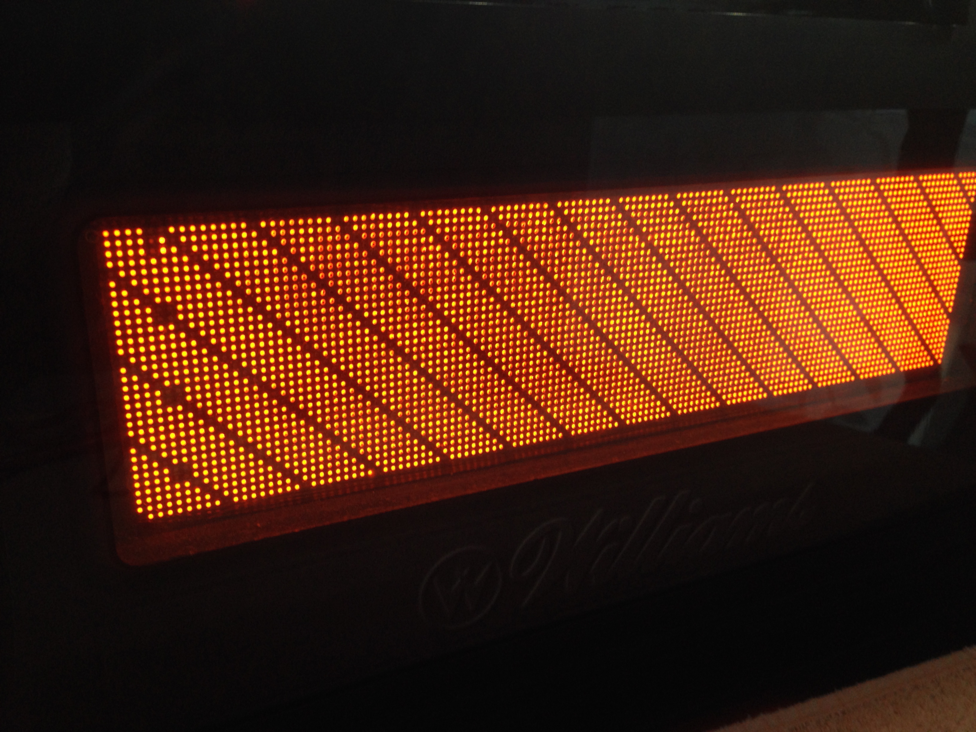
So, what’s wrong with Johnny’s display? Let’s take a look.
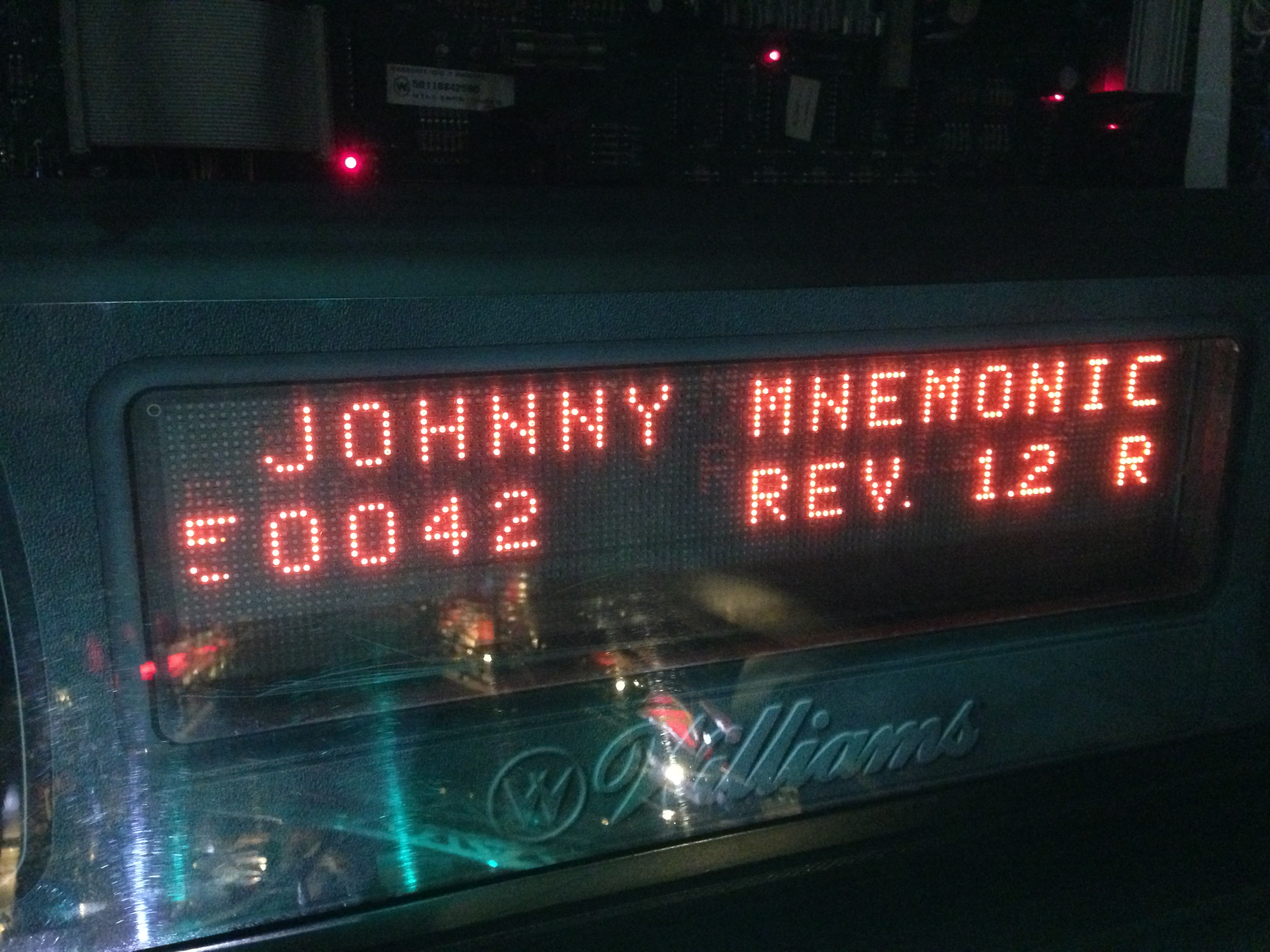
There seemed to be trouble with a couple of the columns near the left edge. Like most things, our first stop is the diagnostic menus. For the display, there’s a large series of test patterns and animation tools to figure out what’s wrong. This is great, because there’s a lot that can go wrong with these beasts. Narrowing the field of problems is a critical step. We’ll start with a positive column test, which lights a specific column that you specify. In this case, I went left to right, one by one, until:
So, looking at that, we have a dead column on the display, right? Well, not exactly. In fact two columns, #5 and #6 are showing these same symptoms. But wait!
This is a strange problem indeed. If a column or two was consistently 100% dead, that would almost certainly be a bad connection on the paper ribbon cable running from the display’s control PCB to the glass plate containing the plasma. This is a pretty common problem. For the stout of heart, it can be fixed by very carefully drilling into the glass to reveal the contact for the column in question, and running a jumper to bypass the bad joint. However, our two bad columns work under certain specific conditions, so this isn’t a ribbon cable problem.
Luckily, there are more intricate tests we can do to try and learn more. There may be more than one issue here, so we’ll focus on the two dead columns.
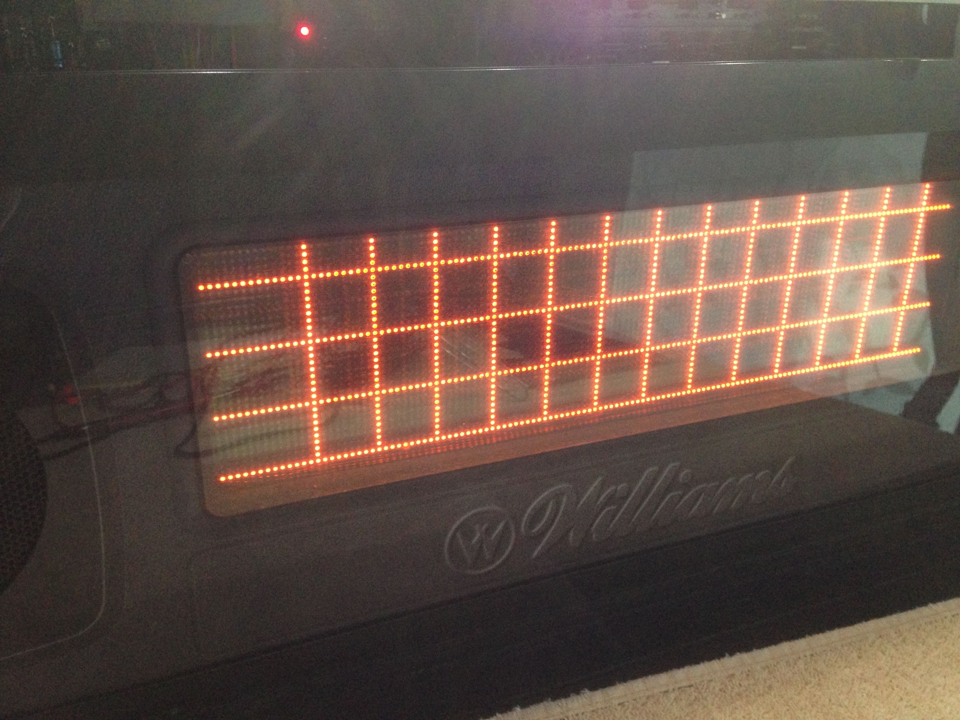
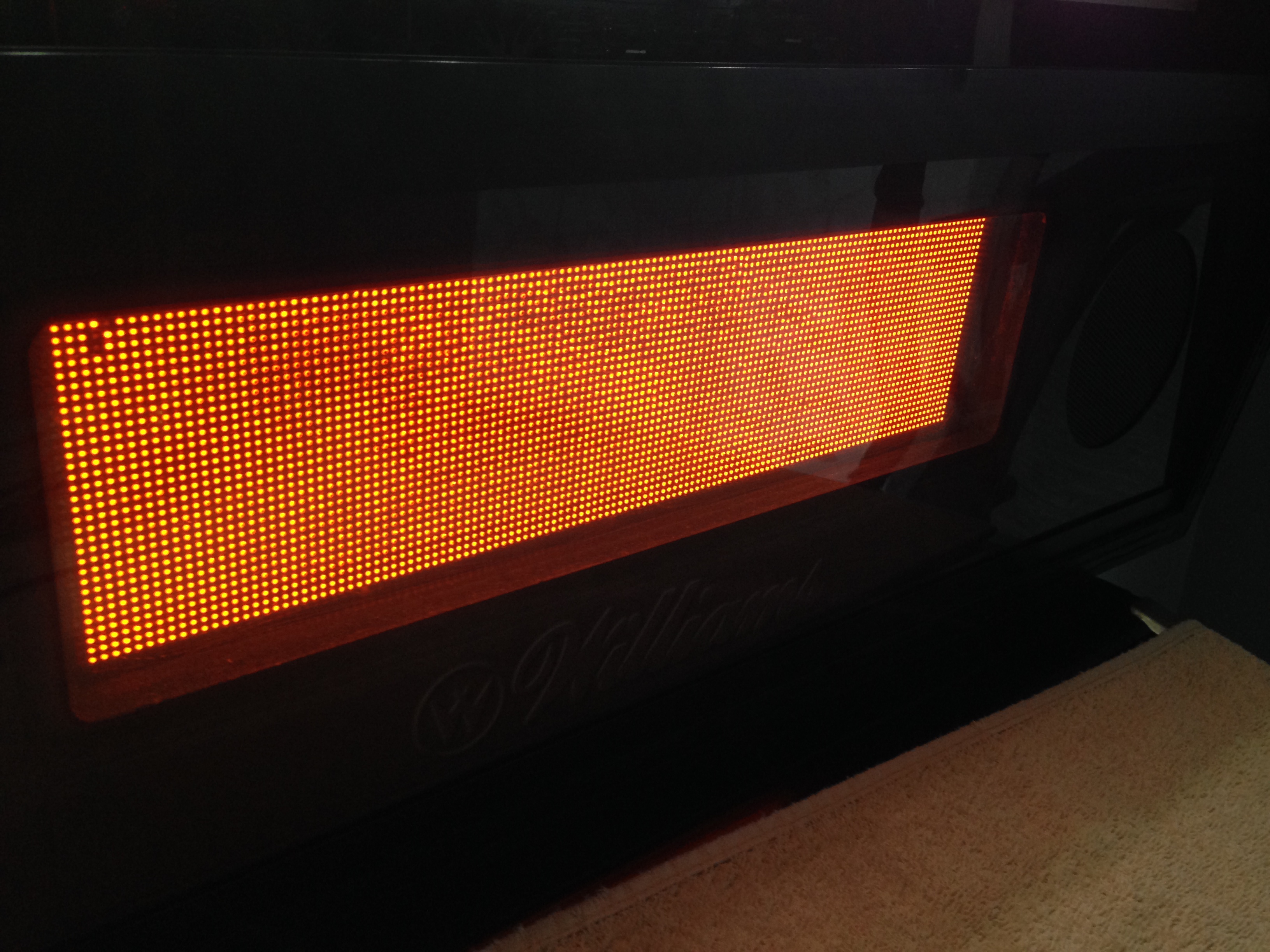
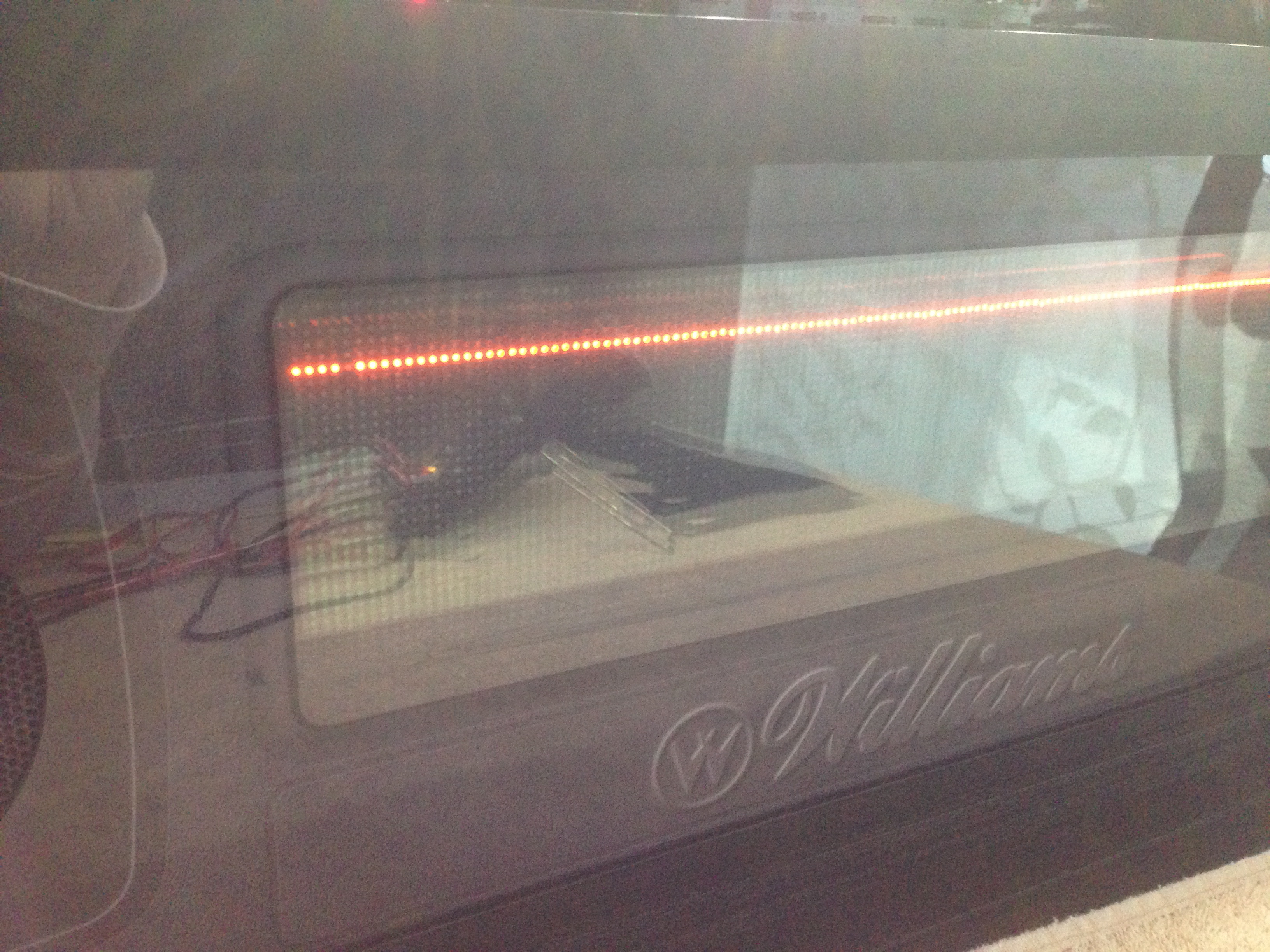
This result is fascinating. If the whole column was dead, we wouldn’t see unbroken horizontal lines on the grid. So, the column is dead only if the nearby columns are inactive. This seems to jive with the solid-fill test. All dots on all rows are active in that test, so both dead columns work (ignoring those rogue dots for the moment).
Let’s see if we can verify this hypothesis another way.
That test confirms that columns 5 and 6 both work if and only if both adjacent dots on the same row are lit. If a dot in column 5 is unlit, it kills the same dot in column 6, and vice-versa.
Having learned what we can from the tests, it’s time to crack this sucker open.
We’ll start with a small sidebar. Because these are high-voltage devices, their power supplies are working very hard. This means they are subjected to thermal stress, and thus tend to wear out and fail. Interestingly, a failing power supply on these displays produces some very unintuitive symptoms. You’d think the whole display would simply get dimmer or something. In fact a bad power supply can cause missing sections, localized flickering, waviness, and other unexpected behaviours. So, the rule of thumb is to always verify the health of the power supply with any DMD problem.
The back of the display has a power connector and a data connector. The schematics for the control board tell us what the voltages should be at all the pins on the power connector.
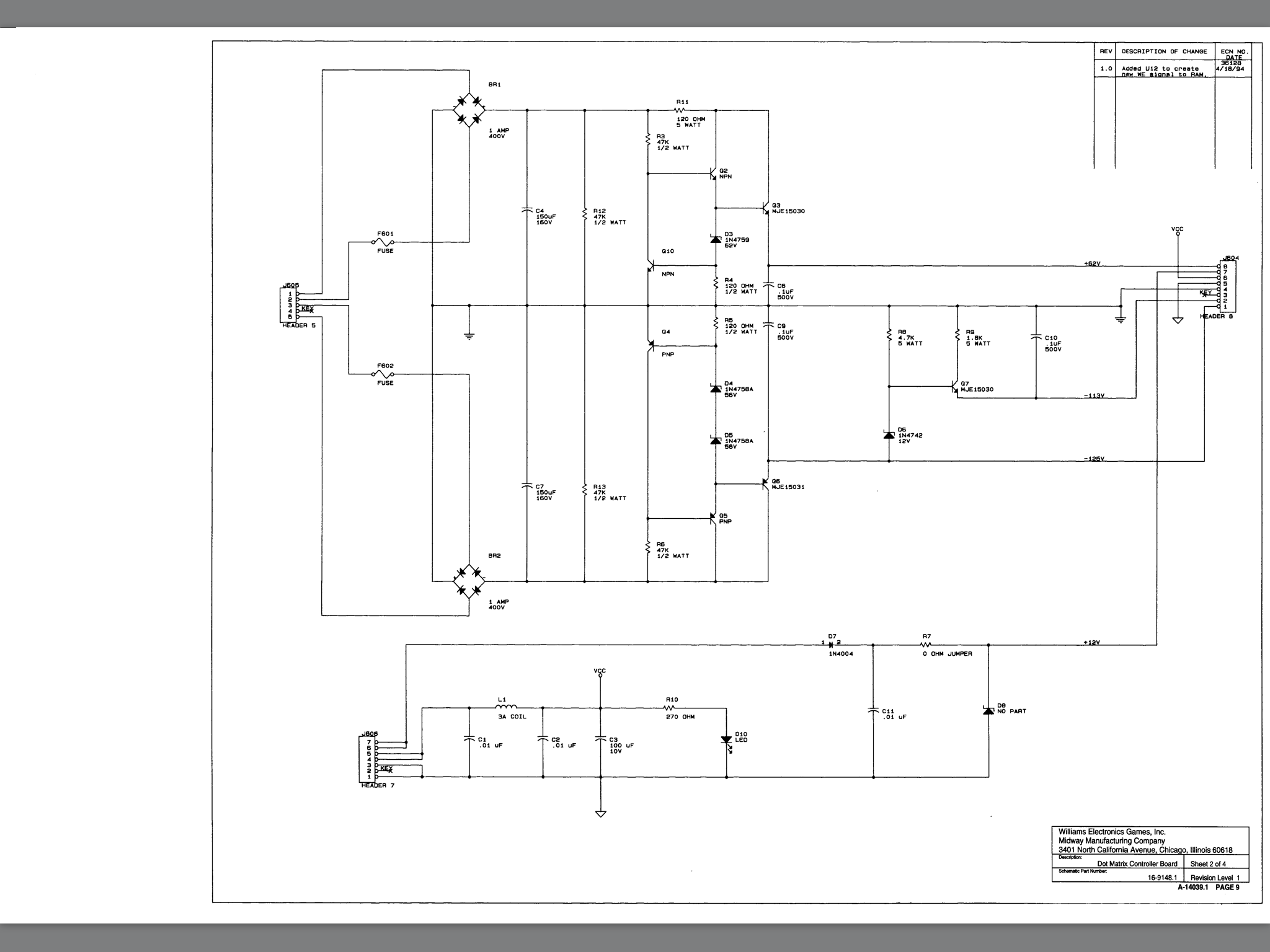
That scanned schematic may not be readable for you, but the pins should be:
- -125VDC (orange)
- -113VDC (blue)
- (keying pin)
- Ground (black)
- Ground (black)
- 5VDC (gray)
- 12VDC (black/yellow)
- 62VDC (brown)
This colorful assortment of voltages is needed because the plasma has to be pre-charged with a high baseline voltage. This decreases the response time of the dots to an acceptable level. A smaller offset voltage can then be applied on top of that to flip dots on and off. There’s also a dedicated pulse width modulation line which further modifies this charging process to change dot brightness. Then, of course, the TTL logic driving communication with the game needs its own stable 5V supply. Interestingly, the 12VDC line (pin 7) is not used by the Vishay panel in my game. There are some similar plasma displays on the market that do need a 12VDC supply (and some that don’t use the other values), so it appears this power supply is set up to handle many different 128 x 32 panels from different manufacturers. This probably gave Williams flexibility during manufacturing to swap out parts based on what they could source at the time. Smart!
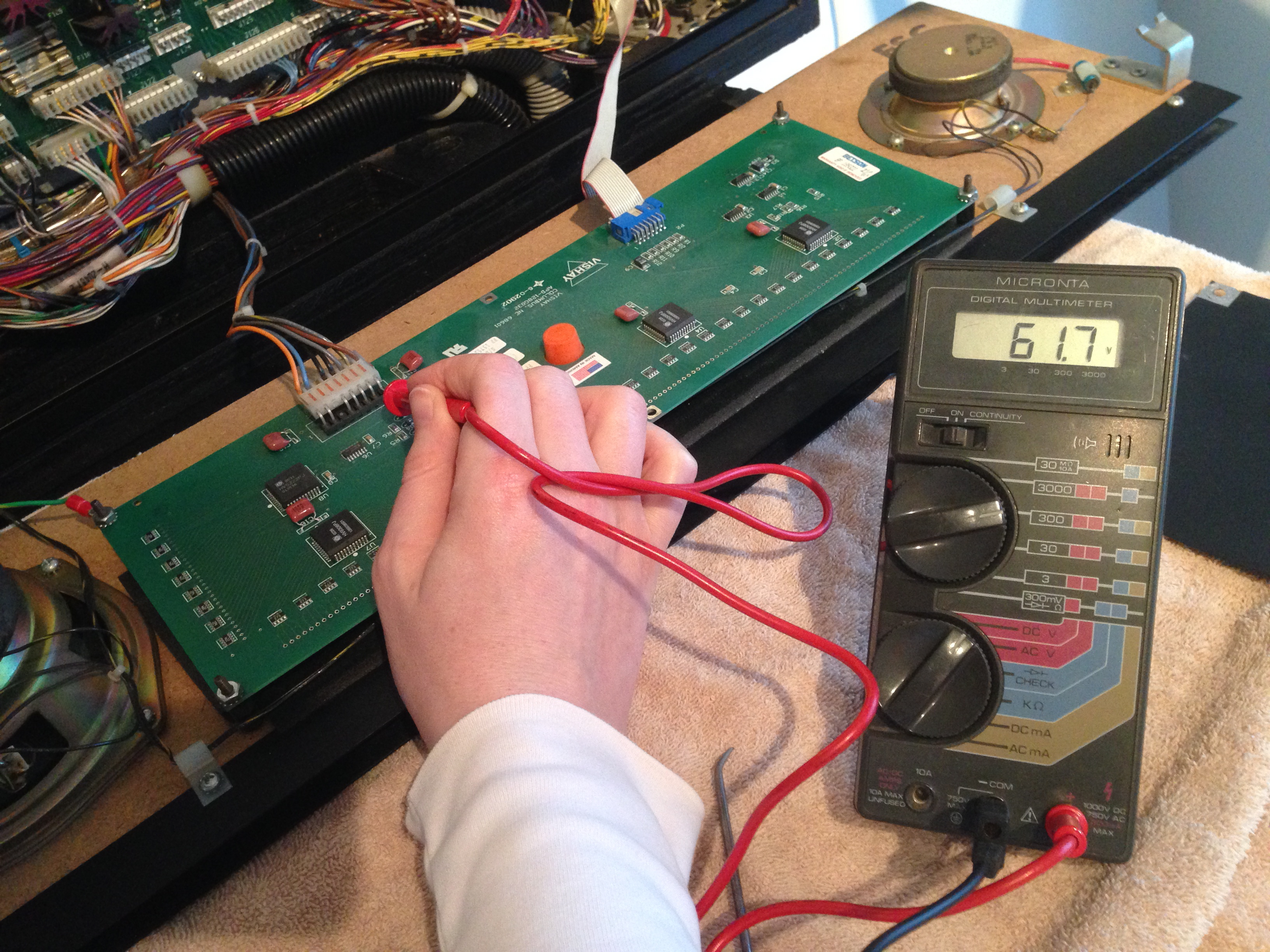
A quick reminder about safety. In addition to the high voltages, the DMD power supply can source substantial current, in the range of 2-3 amps. This is sufficient to murder you quite dead. When probing live circuits like these, clamp one probe to ground, put one hand behind your back, and don’t touch the machine with your body while probing with the other hand. This reduces the chance of current traveling through your heart if you should happen to slip and touch a soft fleshy bit to an electrical bit.
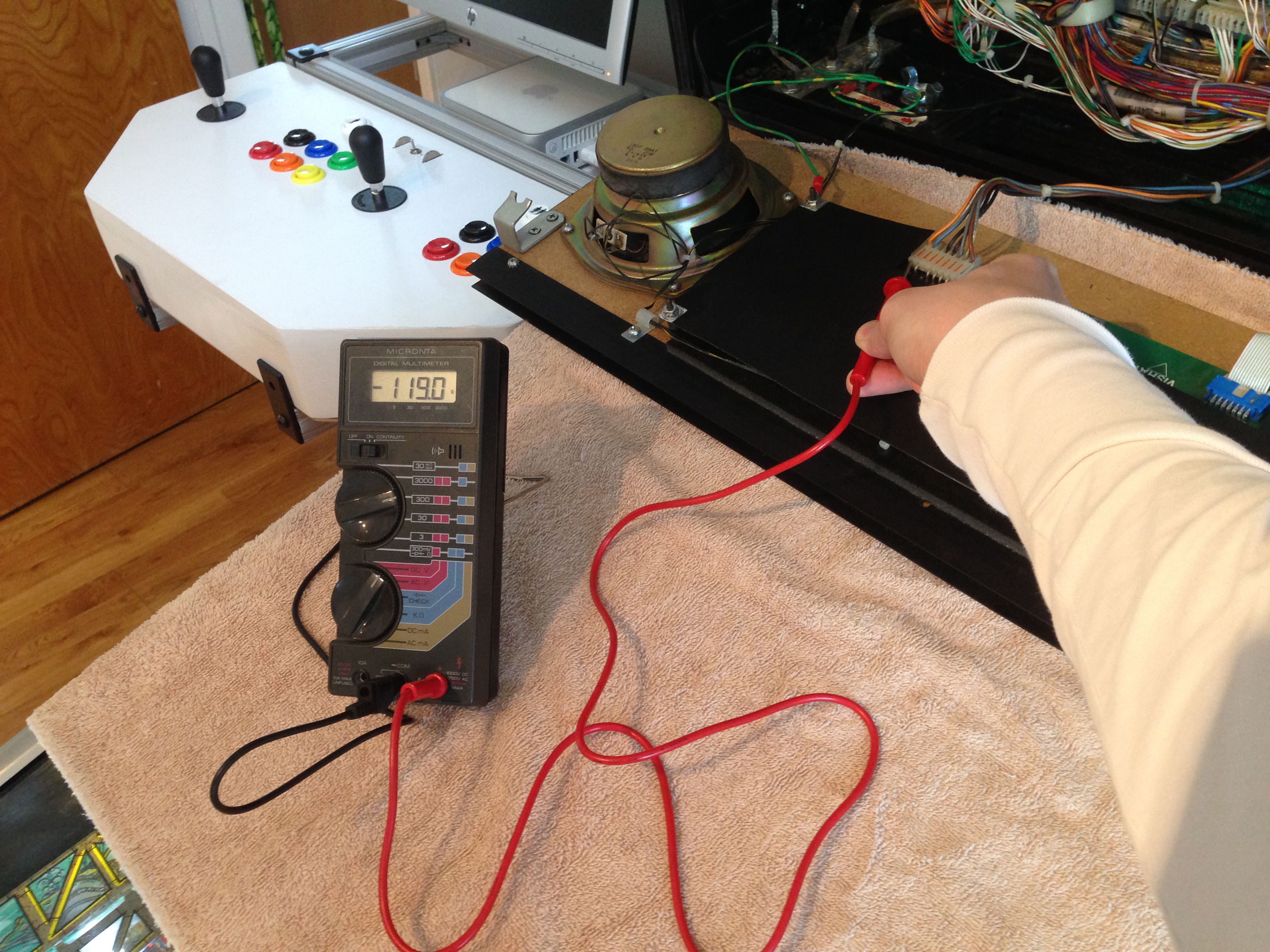
Here are all the voltages I measured:
- -119.0 VDC
- -108.1 VDC
- –
- –
- –
- +5.0 VDC
- +12.4 VDC
- +66.3 VDC
One would expect the power supply to vary from the spec by half a volt or so, but mine seems to a full order of magnitude worse than that. ±6 volts out of spec is pretty alarming! Or is it?

You probably can’t read the scan, but in the bottom left, it lists the expected voltages on the panel’s power connector. They are:
- -120VDC
- -108VDC
- (key)
- GND
- GND
- +5VDC
- +12VDC
- +60VDC
That tells a slightly different story, and in fact matches some of our measured voltages quite well. There’s one other test we can do that might be interesting- disconnect the panel, and measure the output of the power supply directly. I ran this test, and compiled all the results:
| Pin | Williams Spec | Panel spec | Measured loaded | Measured unloaded |
| 1 | -125 | -120 | -119.0 | -117 |
| 2 | -113 | -108 | -108.1 | -95.0 |
| 3 | (key) | (key) | (key) | (key) |
| 4 | gnd | gnd | gnd | gnd |
| 5 | gnd | gnd | gnd | gnd |
| 6 | +5 | +5 | +5 | +5 |
| 7 | +12 | +12 | +12.4 | +12.2 |
| 8 | +62 | +60 | +66.3 | +64.5 |
To add more confusion, the official schematic is for a Babcock DMD panel, but the panel in my game is a Vishay. My panel may not be original, although I can tell it’s been in the game for a very long time (certainly going back to when it was in arcades). It’s difficult to reconcile all this conflicting data and know what’s right. I think we can make some educated guesses, though.
This power supply gets a mixed review. The most important spec is that the difference between the cathode supply (pin 1) and the cathode control (pin 2) is equal to 12 volts (±1V). It’s on the edge of spec when loaded, but out of spec by quite a bit when unloaded. I’m honestly not sure if the measurements while unloaded are meaningful. I’ve seen some sources suggest that the power supply needs the load of the panel to operate 100% correctly, so the readings will be off in this case.
My conclusion from all this is that the power supply is working well enough to drive the display, but it is probably a bit sickly. The anode supply (pin 8) is flirting with being out of spec, and a visual inspection of the board suggests problems. We’ll revisit this power supply in a moment, but let’s get back to the display.
Assuming the power supply is acceptable, it seems we have a logic issue or a glass issue. Since the panel’s interface is serial, there’s a set of shift registers that distribute this data to the rows and columns of the glass. There could be a problem there, causing our weird behaviour in columns 5 and 6. It’s also possible that the logic driving the panel from the CPU is incorrect. This could be caused by a bad SRAM on the frame buffer, or a bad shift register feeding into the serial data line for the panel. We need to run more tests.
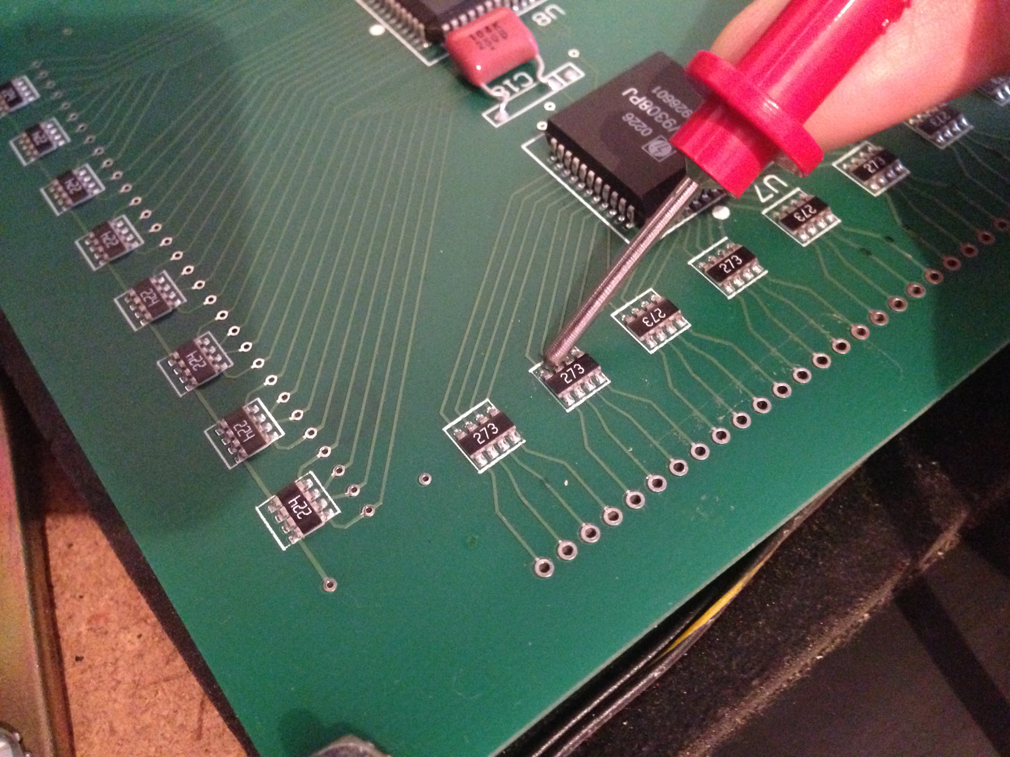
With the panel exposed, but the game powered up, I brought up the positive single column test.

With this, I can test the voltages on each column one at a time. I can compare a known working column (#4) with my bad ones (#5 and #6). Behind the insulating panel on the back of the display, there are convenient test points for checking row/column health.
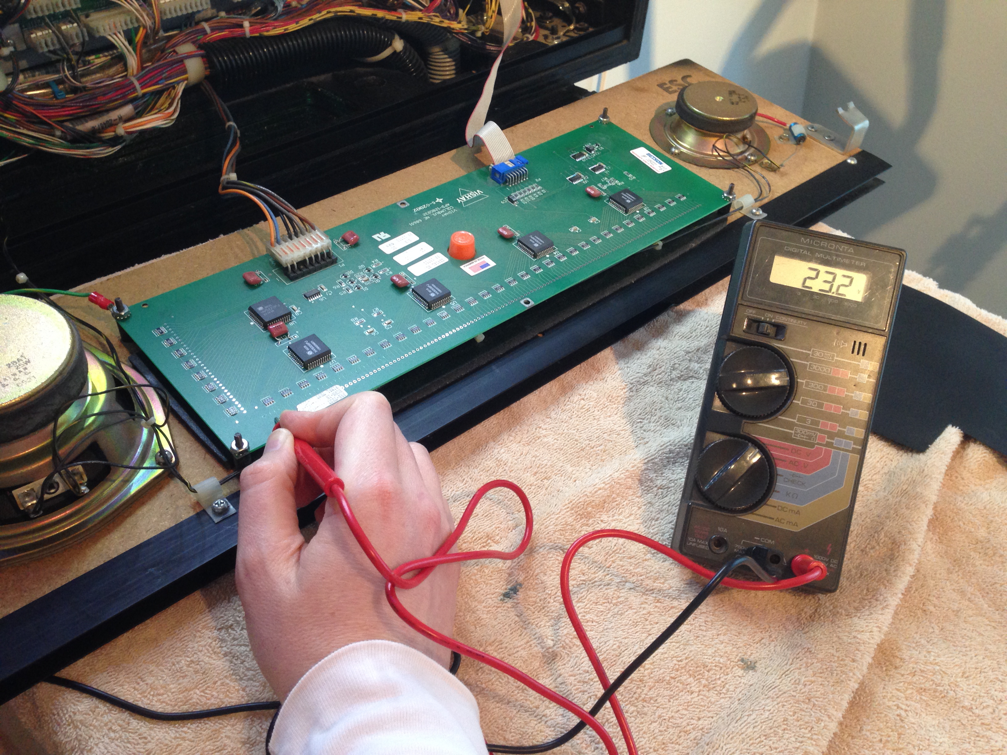
This is where I got my first interesting data point. The two bad columns read 28.8V. A full five volts higher than working ones. Then I discovered something really interesting. When a bad column is energized, the other bad column also reads the same voltage. It’s starting to seem like maybe we have a short between these two columns. Let’s do some unpowered tests now.
This is a good moment to revisit safety. Take a look at this:
The power supply has some very large capacitors in it, and the panel itself stores a lot of energy for a long time after being shut off. Give the panel lots of time to discharge before sticking your fingers on it.
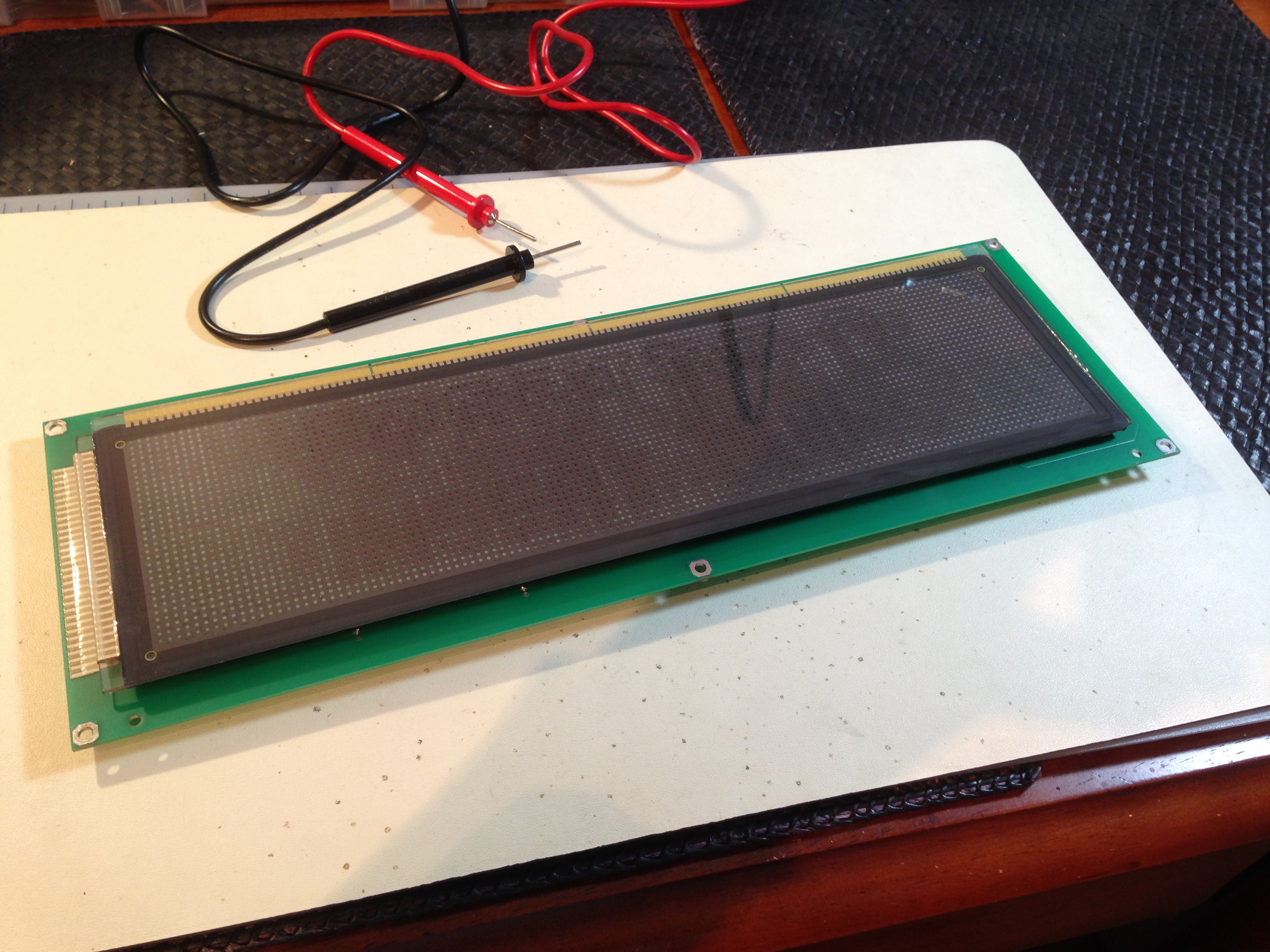
Let’s disconnect this panel and bring it to the bench for further inspection.
At this point, it looks like we may have a short between columns 5 and 6, or we may have a bad logic chip. Let’s take a look at the driver logic on the back of the panel.
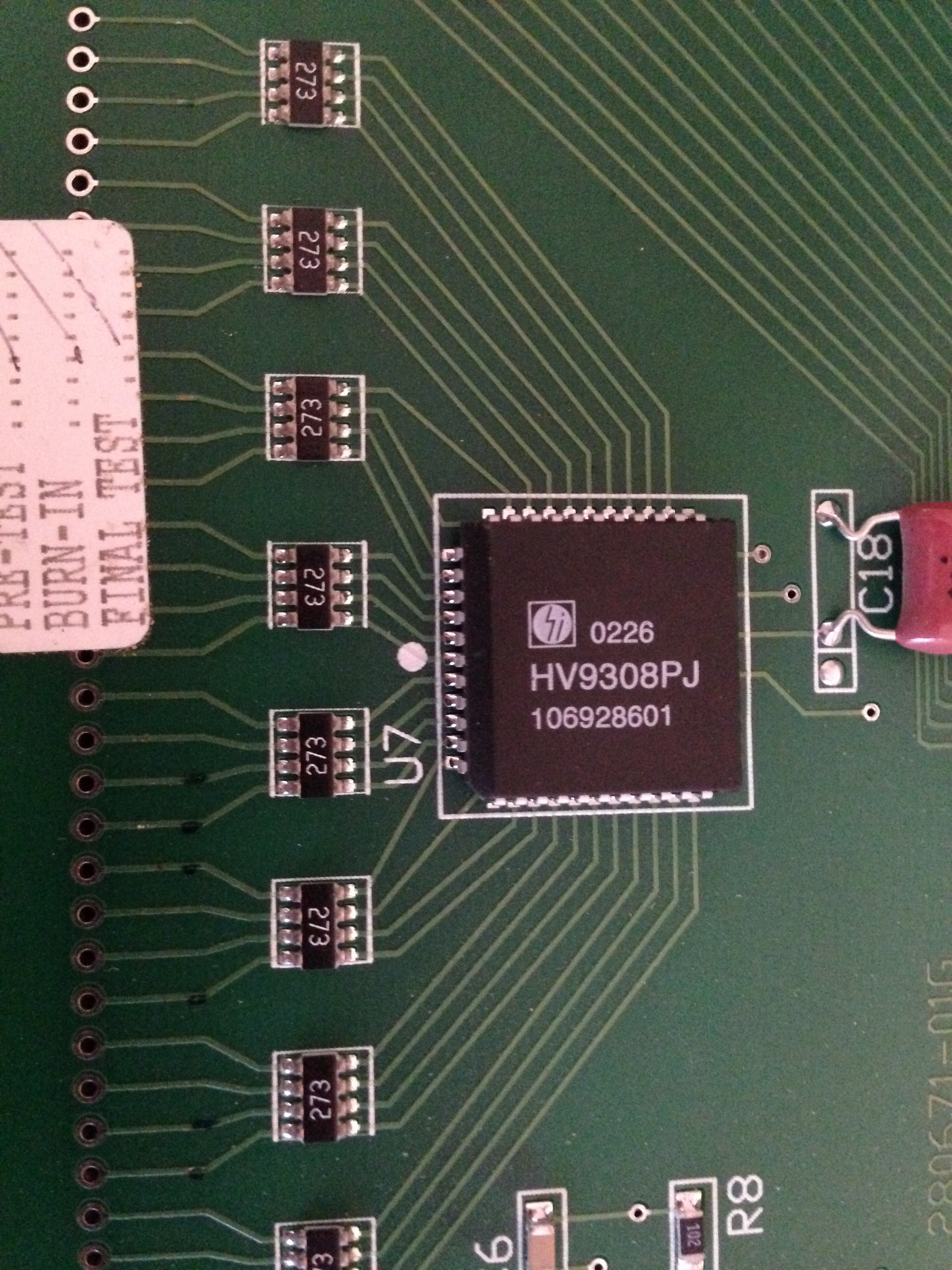
That HV9308PJ chip is quite a neat device. Here’s the datasheet for it. It’s a low-voltage-serial to high-voltage-parallel shift register. Low voltage TTL logic bits go in the serial pipe at one end, and high voltage parallel bits come out the other end. That’s sexy silicon, and just the thing for driving high voltage columns on a plasma display!
Back to our tests. Checking continuity between columns 5 and 6- sure enough we have a weak short of about 1.1kΩ. Good thing it isn’t a dead short, or the panel would probably be six feet under by now, possibly taking the power supply and/or a lot of fuses down with it. It would be a glorious blaze of orange plasma death, though.
Let’s see if we can isolate the short. It could be on the PCB here, or inside the glass.
The chips marked “273” are inline resistor packs (27kΩ, hence 273). These match the schematics for the Babcock panel, which lends further evidence that the Vishay panel is equivalent (and casts further suspicion on my power supply’s health).
On the columns’ test points, I measured the short as 1.1kΩ. Upstream of the resistor pack, I measured the short as 55.1kΩ. That’s bad news, I’m afraid. It means the connection is traveling down though the resistor pack and back up:
27k + 27k + 1.1k = 55.1k
…which means the short is downstream of here. That means it’s inside the glass itself. Shit.
At this point, as much as I hate to say it, I have to throw in the towel on a repair. I really hate replacing things if there’s any chance of them being fixed, but there’s no possible way a short inside the gas-tight sealed glass layers could ever be repaired.
However this is Blondihacks, and if we can’t fix it, we at least want to know exactly how broken it is. Maybe we can deduce the location of the short inside the panel, and from there make a forensic guess about why it failed.
To learn more, I hooked the panel back up and ran some positive horizontal line tests.
These tests seem to localize a spot in the upper left corner where the short seems to be. Probably at dot (5,5) ± 2 dots. Another clue- there’s a small chip in the edge of the glass, at the upper left corner. My guess is somebody dropped the panel on that corner at some point, and it caused an internal short near that area. That short causes the rogue dots, and the curious interrelationship of the two bad columns. As much as it pains me to say it, this panel is going on the junk pile, and a brand new one is going in Johnny.
Incidentally, there are drop-in LED replacements for these panels nowadays, but strangely they are more than twice the price of buying a new plasma. I’m opting to replace the plasma with the same unit, both to save money and for the nice original look. Much like converting the playfield to LED, converting the display to LED can introduce issues with the color shading and animations. The way plasma dots blur and blend has been incorporated into the artwork, so changing the lighting technology will never look quite right. It’s a lot like playing old arcade games on an LCD monitor. The graphics were designed to look good on a blurry, scanline-riddled CRT. On a crisp, modern LCD, they look wrong.
With a new display ordered, and my credit card giving me dirty looks, let’s turn our attention to that ailing power supply. A bad plasma can take down the power supply, and a bad power supply can take down the plasma. It’s best to rejuvenate both at the same time.
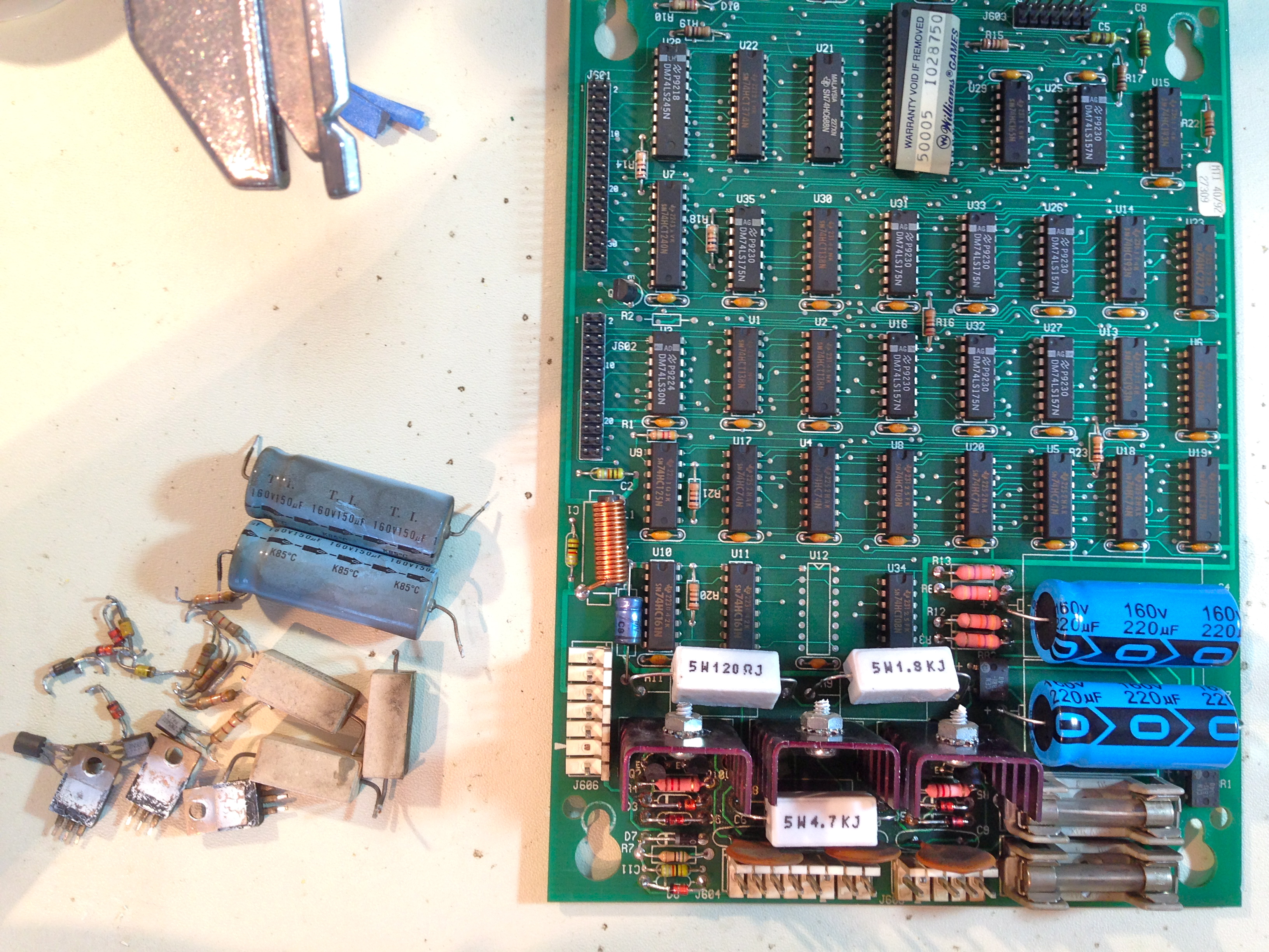
Here’s the DMD controller board in its native habitat.

Here’s the basic anatomy of the board, with the different functional blocks labelled. It takes 100VAC directly from the main transformer secondary winding, then rectifies that and smoothes it. This acts as a shared “pre-stage”. Hanging off the end of that pre-stage are four separate regulated power supplies for the 12V, 62V, -113V, and -125V sources needed by the DMD.
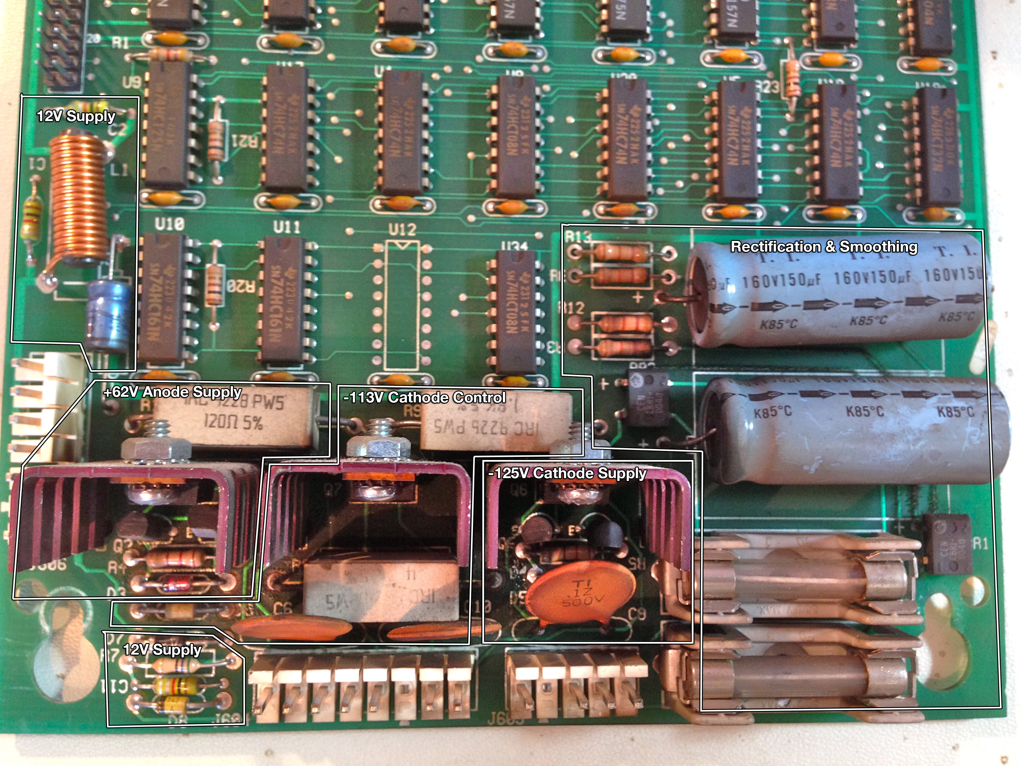
The three big supplies are constant current drivers with the voltage regulated by a set of zener diodes. The -113V supply has a pair of 56V zeners in series to regulate voltage, and the -125V supply then adds an additional 12V zener on top of that. The design compensates for source fluctuations and diode leakage caused by high temperature with additional control transistors. It’s an excellent design, but it has a lot of thermal stress. The big power resistors, in particular are working very hard. We’re going to rebuild this whole system, and take some simple steps to improve its reliability.
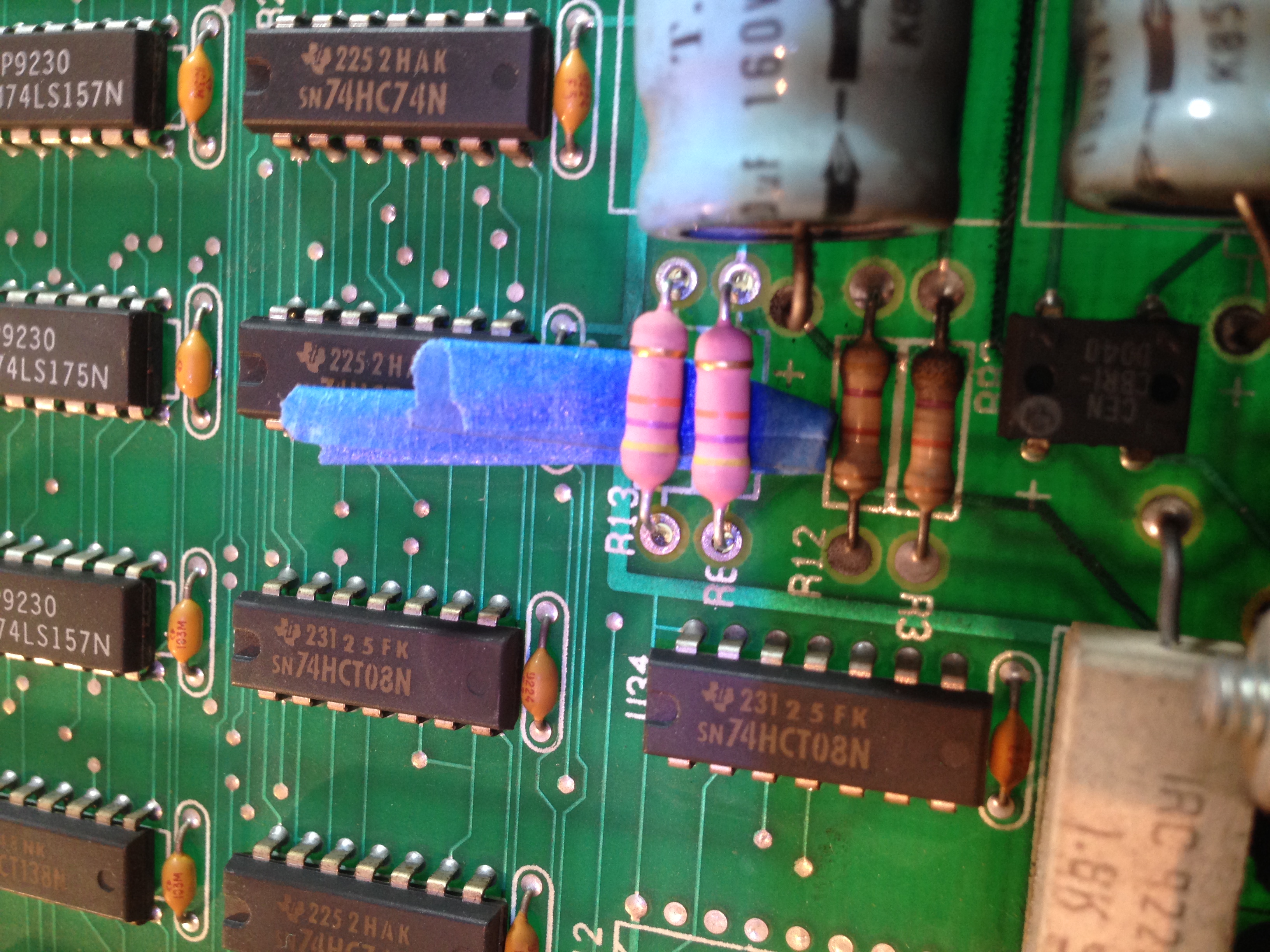
To drive home this point about thermal stress, take a look at the underside of the board.
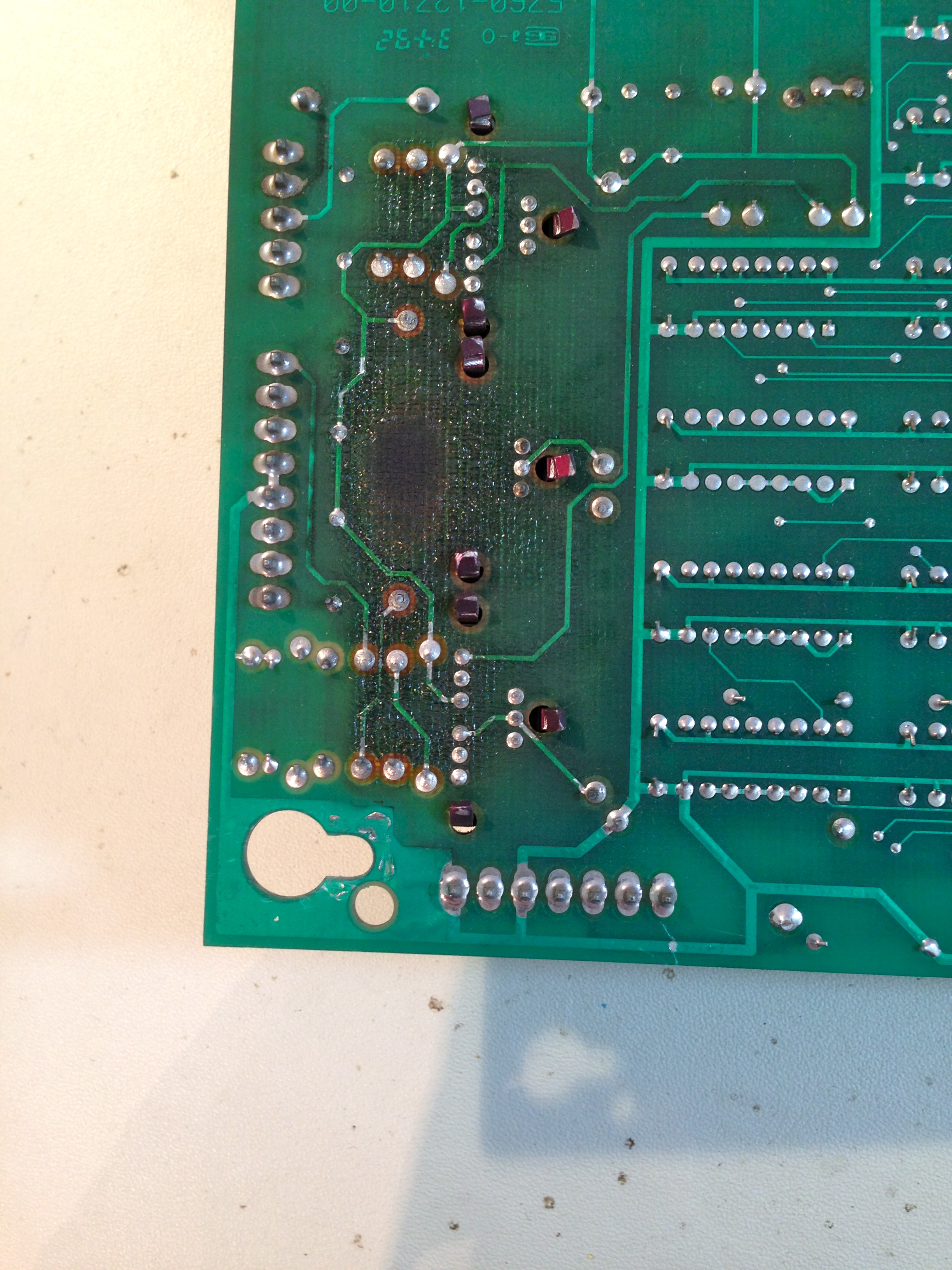
What we’re going to do is simply replace every component that may possibly be worn out with a modern equivalent. We can tell if a component is likely stressed by where it is in the schematic, and by how much charring is on the PCB in the surrounding area. Essentially, every component in the high voltage areas fits this description. We’ll also replace the big electrolytic capacitors, since we all know those things are time bombs.
We’re going to be desoldering a lot of components from a 25-year-old PCB. This needs to be done with care to avoid lifting traces, damaging solder mask, and breaking vias. I would personally not attempt this with clumsy desoldering tools like braids, syringes, or bulbs. For a job like this, there is one weapon of choice.
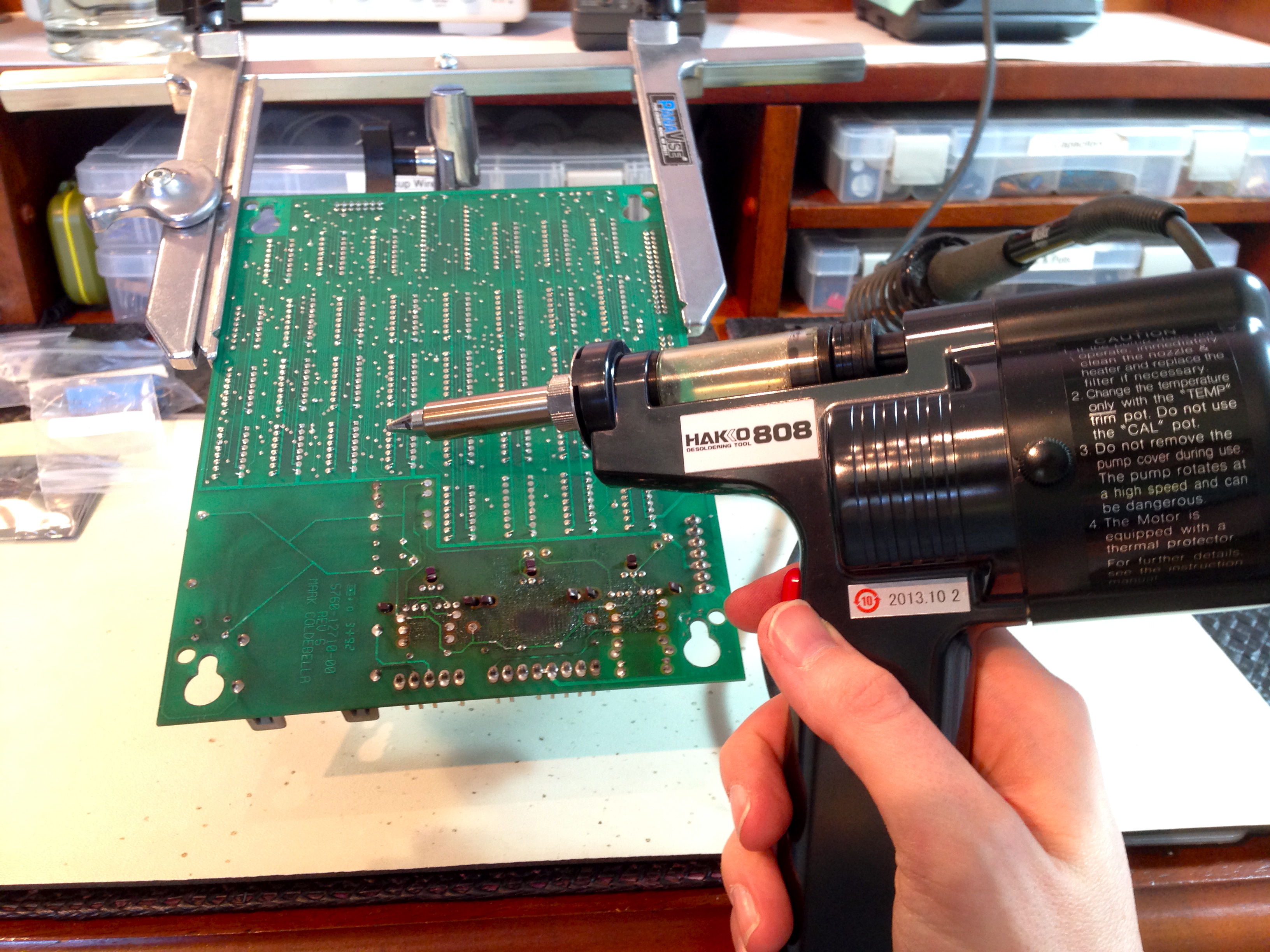
The Hakko 808 is completely self-contained. It has a hot tip like a soldering iron, and a small vacuum pump built into the handle. The whole thing is about the size of a large soldering gun. You press the tip to the joint, wait a second for the solder to liquify, then push the button to suck it up. It’s so fast that it cleanly removes every molecule of solder from the joint without even warming up the component. It also leaves the hole completely clear and ready for a new component, unlike most desoldering methods.
There are some tools which make a job a little easier, and they’re nice to have around if you can afford them. Then there are other tools which take a miserable, difficult job and magically transform the work into something perfectly painless, idiot-proof, and even fun. The Hakko 808 is firmly in the second group. I wish I had bought this thing years ago. I weep when I think of all the time I wasted with bulbs, wicks, and other desoldering techniques that ruin components and don’t really work. I’ve already planned to name my first-born IDT7200L, but my second born may well have “Hakko 808” on their driver’s license.
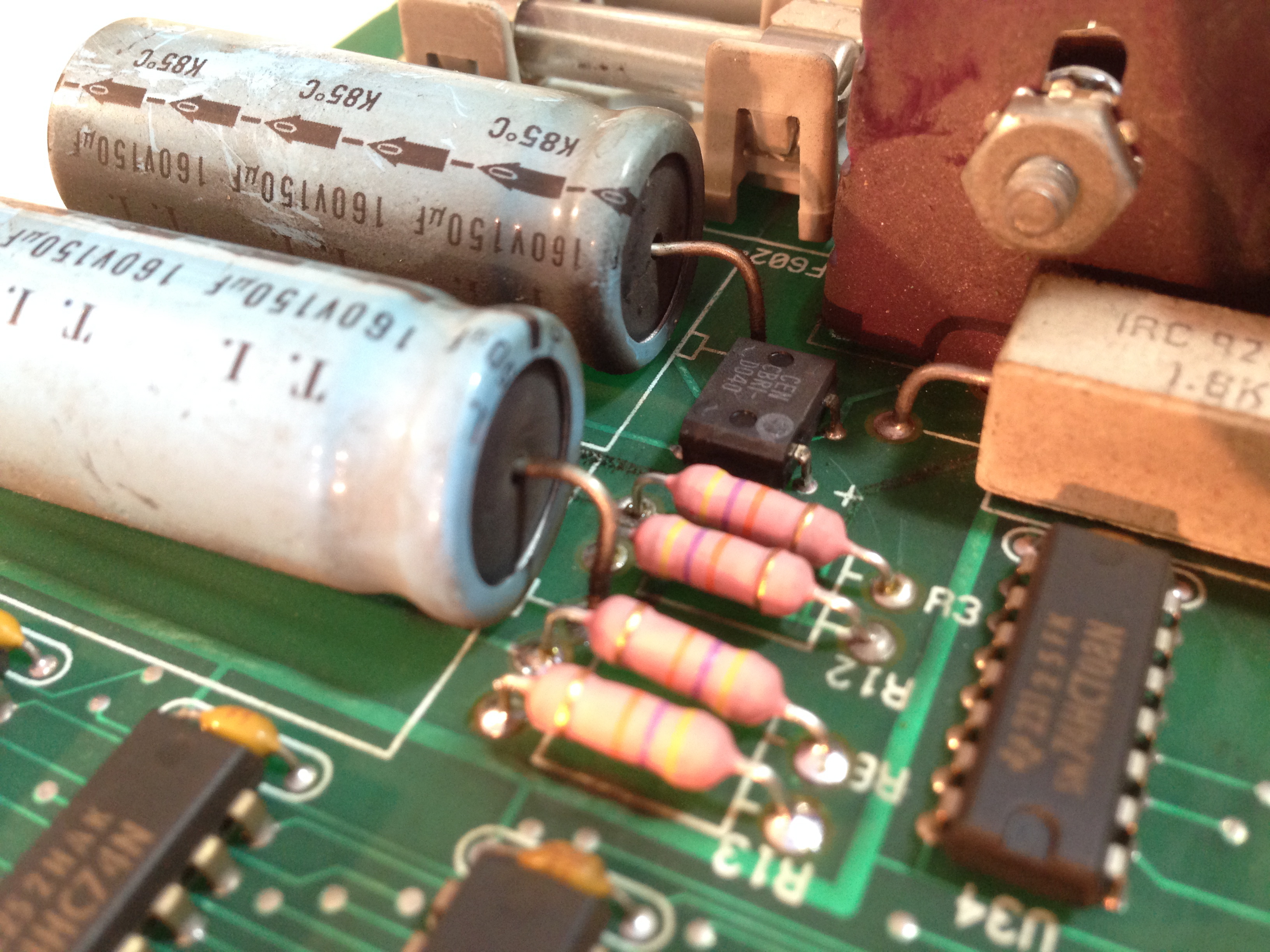
With that fan-gush out of the way, let’s get down to business. The basic approach here is to desolder one or two components at a time, and carefully replace them with new equivalents. A minor upgrade here or there can be useful. A technique I use on every component is to solder them in place floating above the PCB by a few mm. This simple step improves air flow around the components, and makes it much less likely for heat to damage the PCB any further. Air is a lousy conductor of heat, so if the component isn’t touching the PCB, much less heat will transfer. For the bigger resistors, the PCB was acting as a heat sink, and that’s not really great.

As I remove components, I’m also cleaning up the charring (as much as possible) with alcohol. Furthermore, the power transistors have their heatsinks removed, cleaned up, and new heatsink paste applied. Dirt on the heatsinks will reduce their efficiency, and old heatsink paste won’t conduct from the transistor very well. I want this board to last another 25 years!
This is a multi-layer board, so make sure each component lead is soldered all the way through. You should have a nice solder cone on the component lead on both the top and bottom of the board. If the top isn’t well-soldered, sometimes a quick reheat of the joint from the top is all you need. This draws the solder up through the hole all the way.
Note that for the cement power resistors, I floated them quite a ways above the PCB. I used one of the old resistors as a spacer, so they are a full centimeter up in the air, and at least 50mm from any other component. I also bent them back a bit, away from the heatsinks. That’s why they look sort of “sloppy” in the photo. A small aesthetic price to pay for much better thermal performance.
Once the board was rebuilt, I did some basic tests to bring it back online. I plugged in all the cables except the DMD panel itself, then powered it up and measured the outputs at the header. I wanted to make sure nothing was crazy out of line before plugging in my expensive new panel. The readings were all decent, so I plugged in the panel and measured it while loaded:
- -115V
- -103V
- (key)
- GND
- GND
- 5V
- 12V
- 63V
These numbers are not right on-spec as I was hoping they might be, but they are within spec in all cases. The all-important difference between pins 1 and 2 is 12V, which is good. This supply seemed to be struggling before, but now it’s more firmly in spec. With all new components, it should be good for a long time indeed.
With the supply behaving itself, it was time to boot up with the shiny new panel and see what happens!
Looking good, Johnny. Looking real good.
Interesting side note- on the image of Johnny Mnemonic’s face, you can see the pulse-width modulation I talked about. The video is 60FPS, and the refresh rate on the pixels is considerably lower than that, so there’s an interesting flickering interaction with the camera shutter. Of course, in person, all you see is varying shades of orange on his face.
I’d like to close with a quick shout-out to Ed at Great Plains Electronics. He sells all the parts for this job as a nice package, for an amazingly reasonable price. If you don’t have all the parts to do this job sitting on your junk pile, Ed can hook you up.
I haven’t gotten farther than the first sentence, but I’m already laughing. “Hey caareful, man, there’s a beverage here!” One of my favourite movies 😀
I’m looking forward to reading the rest. I’ve been really enjoying this series, despite knowing nothing about pinball machines.
You won’t get any argument from me on that one. The Big Lebowski is pretty close to a perfect film, in my book.
Interestingly, Dutch Pinball has acquired the rights to TBL and is making a game based on it. The new and boutique pinball machines are out of my price range, otherwise I might be on the waiting list for one.
http://www.thebiglebowskipinball.com
That’s…. wow. A pinball game about… bowling. I see so many (awesome) places that could go. I wonder how/if they’ll work a briefcase full of dirty undies into it.
On an entirely related note: when I moved into my current apartment, which is all nice old hardwood flooring, the rules of the building are that you put down rugs in all the “high traffic” areas. The hardwood is quite light, and my furniture is all either black or dark brown… so I found the bestest rug! It’s black bordered, with a sort of off-square grid filled in various shades of brown. It really does tie the room together. Whenever someone new comes over, I make a comment about how it ties the room together, doing my best (hint: not very good) to keep a straight face. 🙂
It’s filthy in this photo, but there’s the rug, the floor, and some of the furniture: http://imgur.com/p8iNX6R
(Yes, that’s a piece of artifical xmas tree tied to an elastic, taped to a chopstick. Despite leaving the tree alone, the cat goes crazy for that little piece of it.)
I think it’s time you gathered up the cat’s friends and had an intervention. He or she needs to get that monkey of their back.
Quinn,
Any thoughts on the heat dissipation? You spaced the new resistors off the PCB but perhaps some heatsinks or active cooling would increase longevity. PC case modders put heatsinks on a lot of components (maybe for show, but they could be repurposed).
Long Live Johnny!
?;-)
That’s an interesting idea. Heat sinks on a couple of the power resistors might be a good idea. Especially R8, which seems to take the most abuse.
Truth be told, there’s so much carbon staining on this PCB that it’s right at the edge of being worth saving. The high voltage areas can arc if there’s too much carbon around, frying things all over again. I’ve squeezed a little more life out of it with this rebuild, but if I’m being honest it probably should be replaced.
Great post as usual!
Pro tip for that Hakko 808: put some steel wool in that glass tube in front of the filter. When it fills up, all you need to do is to pull out the steel wool wad which will have caught all the solder, and the filter will stay (mostly) clean.
===Jac
Hey thanks- that’s a great tip! I heart this thing- I need more excuses to take stuff apart now.
Nice work. the HV in the panels scares me. My SEGA is outgassing and I need to replace it. I dont like the look of the XPIN matrix blocks.. but the non blocked Vishay is expeeeensive. ugh.
Yah, I’m not partial to the “grid” effect the X-Pins have either.
Is your Sega machine the standard 128×32 size, or one of those unusual Sega sizes? If it’s standard, try MAD Amusements. They sell the Vishay panels for about a quarter of what the X-Pins cost, and about half what most places charge for the normal plasmas.
You definitely want to replace an outgassing display. It will kill your power supply in short order.
Treat the high voltage areas with respect, but don’t let it stop you from working on them. Healthy fear will keep you safe. It’s the people who don’t worry about it that get zapped. :o)
Hi, love your blog 🙂
You are measuring higher voltages (abs) with the PSU loaded than unloaded? That is strange – or perhaps just an error?
Cheers
Danish Paul
It is a bit strange, I agree. I did these measurements multiple times, to be sure, and it does seem to be the case. I’m not entirely sure why, though.
The higher loaded voltages could have been caused by excessive ripple due to aged capacitors, older DMMs often have trouble distinguishing between pure DC and DC-with-substantial-ripple. How I know?
My first laptop (‘286 processor, 600×400 plasma display) refused to power-up to a stable working condition one day displaying all sorts of weird behaviour: inoperable keyboard, part of the display not working, spontaneous reboots, random harddisk failures, you name it.
I opened her up and measured the +5V to be +7V. That did not make sense: most of her still somewhat worked, no black smoke had escaped anywhere… After some thought I switched my meter to AC and found 6V(!) ripple on that same 5V line: the primary capacitors (200u/200V) in the PSU were shot. After replacement she served my packet radio station flawlessly for many more years. Eventually the display itself developed brightness issues and she was decomissioned, may she rest in peaces.
Ahhh, plasma displays. In the 80s, when I was a shiny engineer at an avionics company, I worked with plasma displays. In those days, LCDs had challenges meeting the environmental requirements of general aviation. I “fondly” remember, one quite late night, working on some problem with a contol head that had a plasma display, a little 2″ x 2″ one. After like the one thousands mode I made on the unit, I turned it on and picked it up. I suddenly realized I was touching the display’s high voltage lines. My animal brain took over, “drop thing that hurts.” So this unit, that I had been working on to the wee hours of the night, I threw it on the ground. I decided it was time to go home.
I’m ogling over that desoldering pistol. That is all.
It’s boooootiful. Easily among my top five favorite tools now.
Totally unrelated question: Could you do a tour of your lab/bench and your test equipment some time?
That’s a good idea, actually. Maybe I’ll do that!
Your afread of a measly 125 volts? Girl, I’m an old school ham who used to build vacuum tube power amplifiers. I have fond memories of a 1500 Watt final I built that used a pair of 4-400A tetrodes in grounded grid, with almost 4000 volts on the plates! I certainly didn’t take ANYTHING for granted on that one, after powering it down and waiting for the voltmeter to drop to zero, I would short the B+ to ground with a WELL insulated screwdriver. I never drew an arc (doing that with the power on would have welded the screwdriver in place!), but safety first!
BTW that power supply was overbuilt with lots of plexiglass for insulation where it counted, bleeder resistors in parallel (if one opened up the results could be DEADLY), and a single meter for each function (no switched meters).
Now I’m not poo-pooing that “line voltage” supply any, it’s just as deadly as my “Tesla” level supply was. But you don’t know fear until you’ve worked on power supplies with voltages in the ‘Kilo’ region, and survived the effort by showing them the respect they deserve.
With a 1.1K short on the plasma panel, you declared it trash. In that case, would it not have made sense to try and blow (“fuse”) the short open? Hit it with a capacitor full of 125V and see what happens. With a trash panel, what have you got to lose? Either the short opens, or the panel now has another fault, but no less value.
That’s a good question! The reason I didn’t make any more heroic attempts to fix it is that the panel is still valuable in its present state. I can use it as a test panel to swap out in the future, if DMD problems are suspected. There are also people who will buy them in this condition, if I decide I no longer want it.
Nothing new from Johnny? ;-(
Heh- hang in there. More Johnny is on the way. Sometimes work and living in a high-maintenance old house get in the way. 🙂