A tale of fourteen fails.
Sometimes a project goes so smoothly from start to finish that you’re left feeling all warm and fuzzy, and the whole experience is a real thrill. You look back on what you’ve built, marvel at how awesome you are for building such a fine thing so efficiently, and can enjoy the memory for years to come.
This is not one of those times.
You wouldn’t think a 1.5″ square PCB could cause much trouble, especially when you’ve built dozens of such boards before. This is one project where a truly astonishing number of things went wrong, yet I persisted despite myself, ultimately ending up with nothing to show for it. Hold on, I’m getting ahead of myself here.
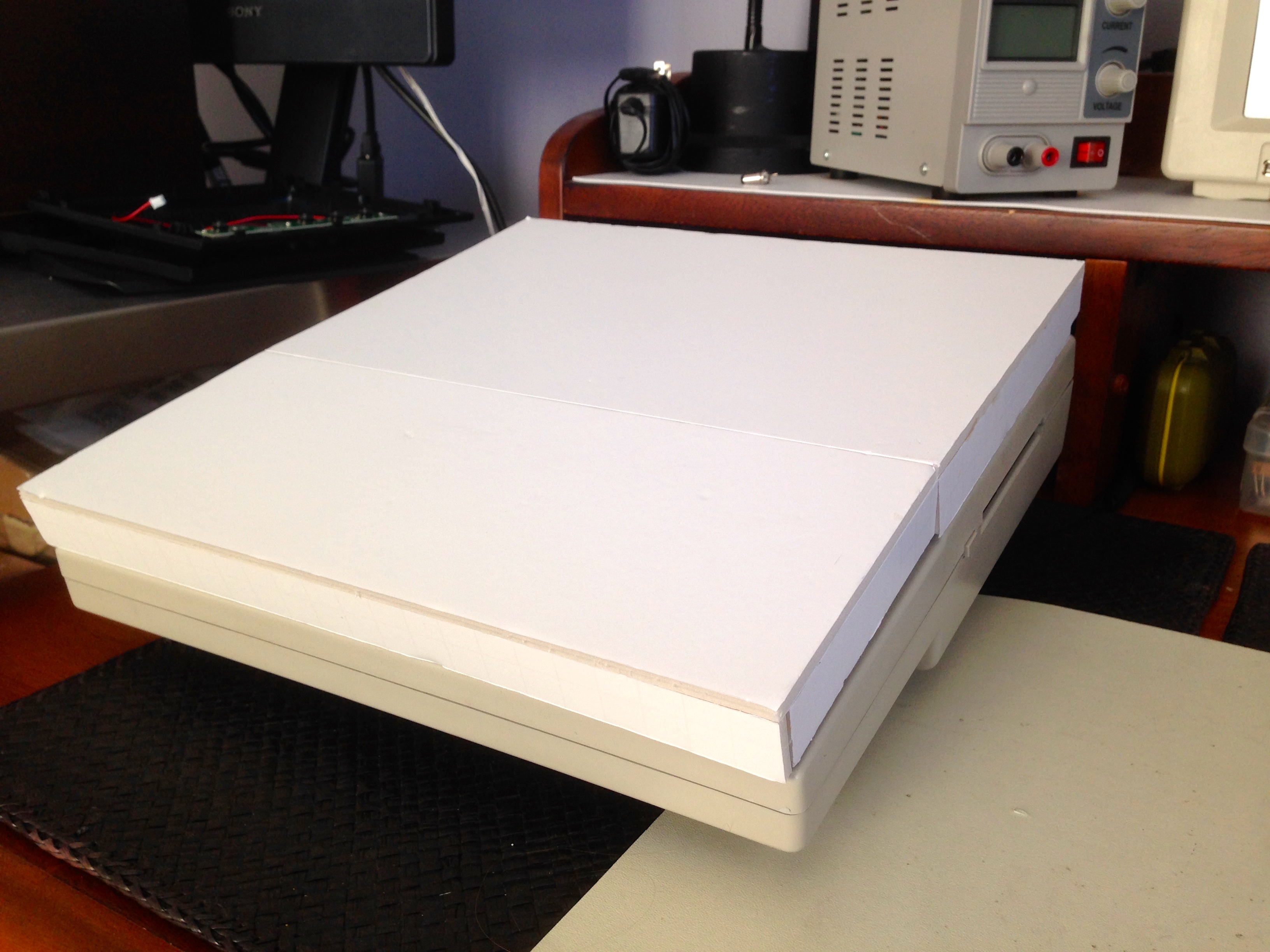
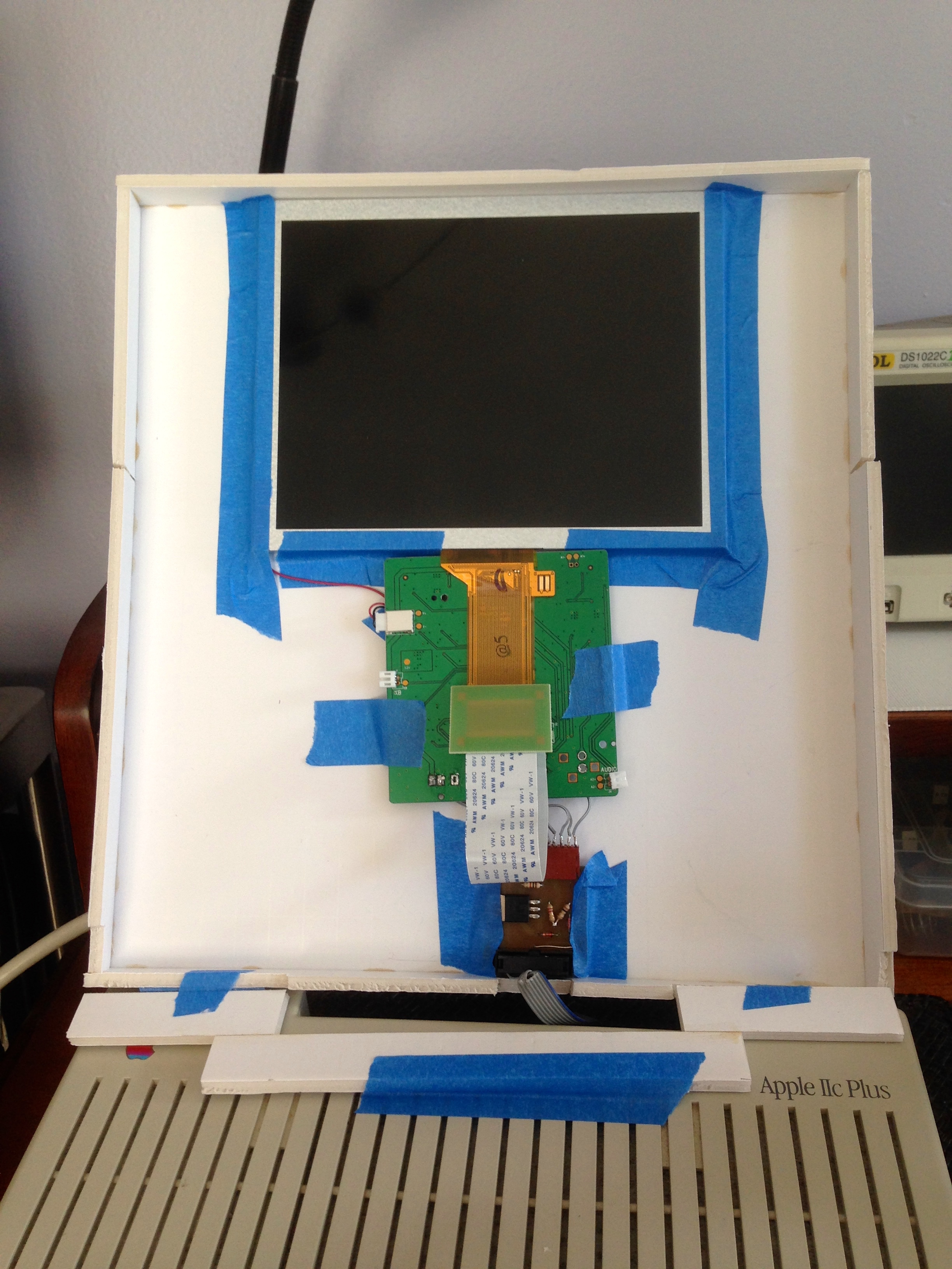
Previously, I got a nice display solution up and running for my IIc Plus project. One of my specifications was that the screen needed to be in the 8-10″ size range. You may have wondered why. The reason is that I’m in the midst of prototyping an add-on product for the Apple IIc and IIc Plus that I’m code-naming Teddy Top. It’s so-named because it lives on top of the Teddy (which was one of the prototype codenames for the Apple IIc computer). Teddy Top is a hinged display that mounts to the top of a IIc, similar to how a clamshell-style laptop works. It serves a similar purpose of protecting the keyboard for transport, while providing a convenient display anywhere you go. In this article, I get started with mocking up the display portion of the Teddy Top.
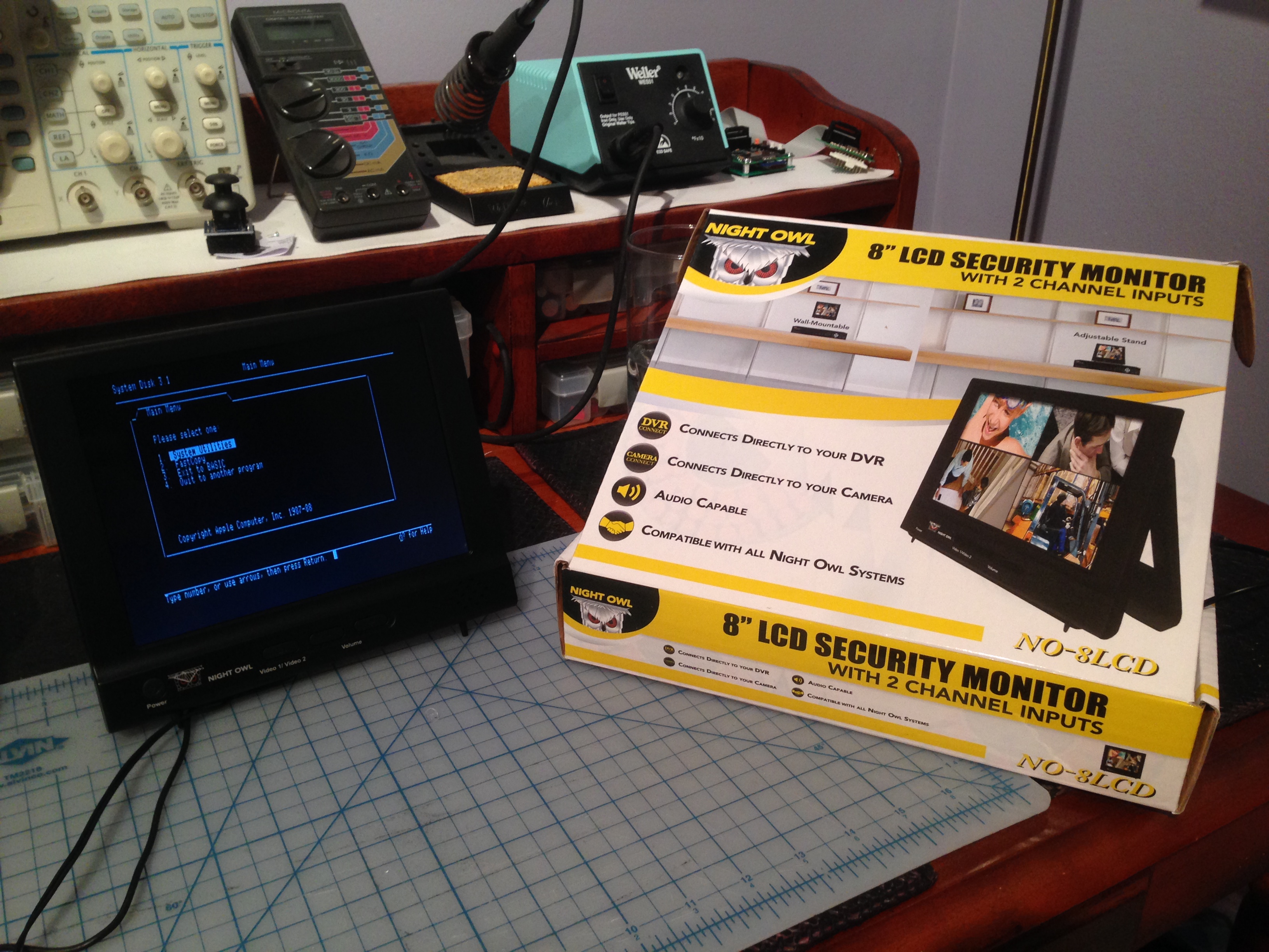
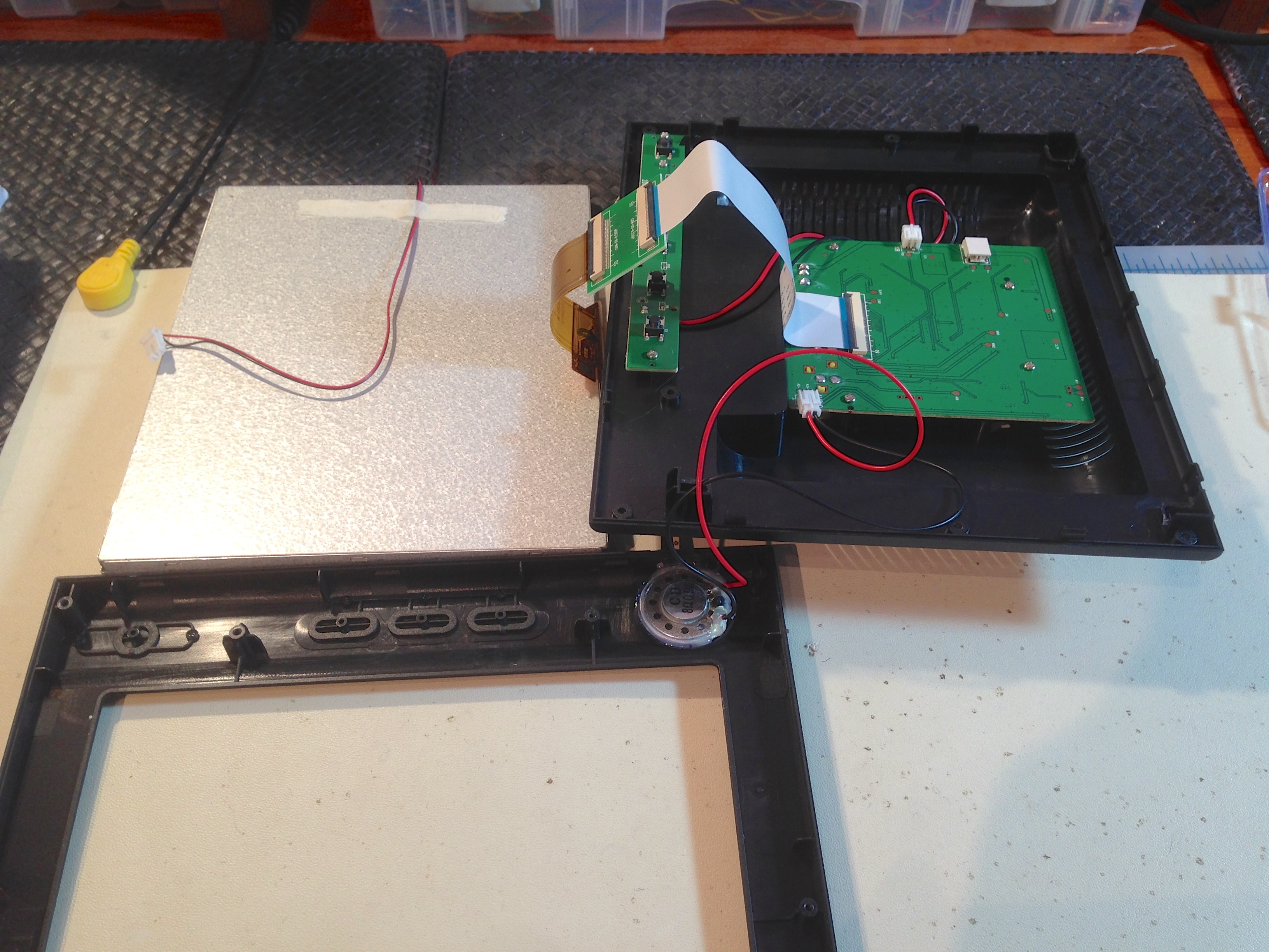
First things first, we need to get inside this monitor and see what we have to work with.
The plan is to drive this display from the IIc’s Video Expansion port. You may recall from a while ago that I was very interested in this port. It’s now time to make good on my threat to hack with it. Here’s the relevant information from the Apple IIc Technical Reference manual on this delightful port.
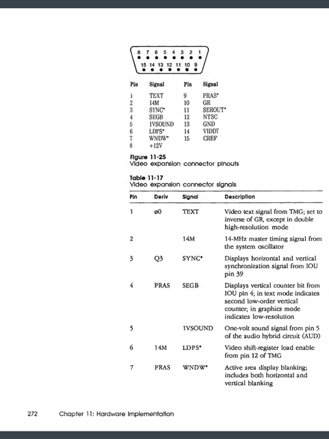
The parts I’m interested in are +12V, Ground, and NTSC video. According to the manual, the 12V source can drive up to 300mA. By astonishingly lucky coincidence, the LCD panel I bought runs on 12V and draws 200mA. However, instead of just marveling at my good fortune, I decided to “do better” than just wiring the panel into the machine. This is where things go very pear-shaped indeed.
My thought was a noble one. I thought to myself, “Self, sure, the ammeter says this panel is drawing 200mA, but can I trust it? What if it spikes sometimes or draws more in some situation I don’t know about? Shouldn’t I protect the poor IIc from such risks?”. I set out to design a little bridge board that would sit between the panel and the IIc to protect it from harm. Little did I know what I was in for.
To start with, I dug up this nice little current-limiting circuit. It’ll work with most any NPN power transistor, and you can tune it to set the maximum allowed current. If the load tries to draw more than that, the transistor will start dropping the voltage and dissipating the excess power as heat. If the load is really high, the transistor will ultimately blow, sacrificing itself instead of harming the IIc. You might be thinking, “why not use a simple fuse for that, then?”. Well, that would be entirely sensible, but Blondihacks is not known for sensibility, and I wanted to try out this neato current limiter. I had many many chances to quit while I was ahead here, yet I proceeded. Not simply installing a fuse and calling it a day was Fail #1. Buckle up, kids- it’s gonna get so much worse before it gets better.
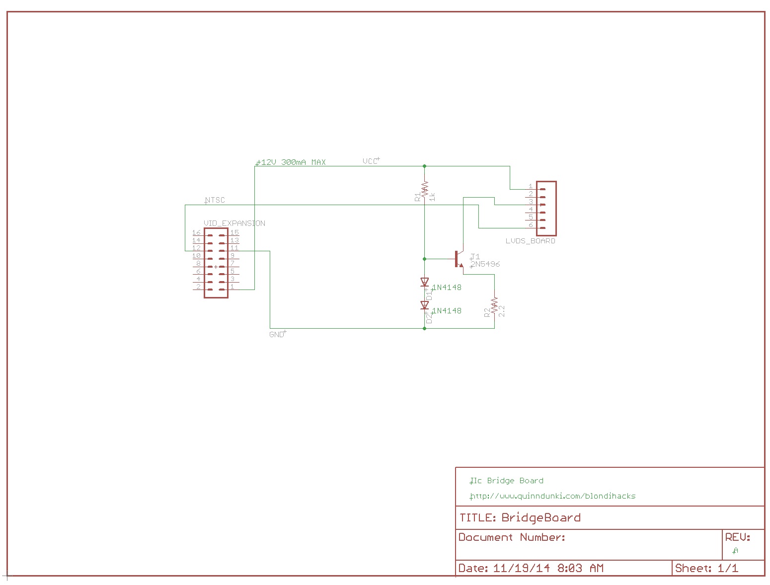
Input voltage can be anything in the 5-15V range. The value of R2 sets the maximum allowed current. The catch with this circuit is that the value of R2 needs to be very precise. Theoretically, I(max) = 0.7/R2. I wanted to limit the current to 250mA, to give a nice safety margin for the 300mA limit on the IIc’s expansion port. In theory, that means I need R2=2.8Ω. In reality, the value depends on the exact implementation, so it needs to be dialed in experimentally, as we’ll see. However, that equation is a good starting point.
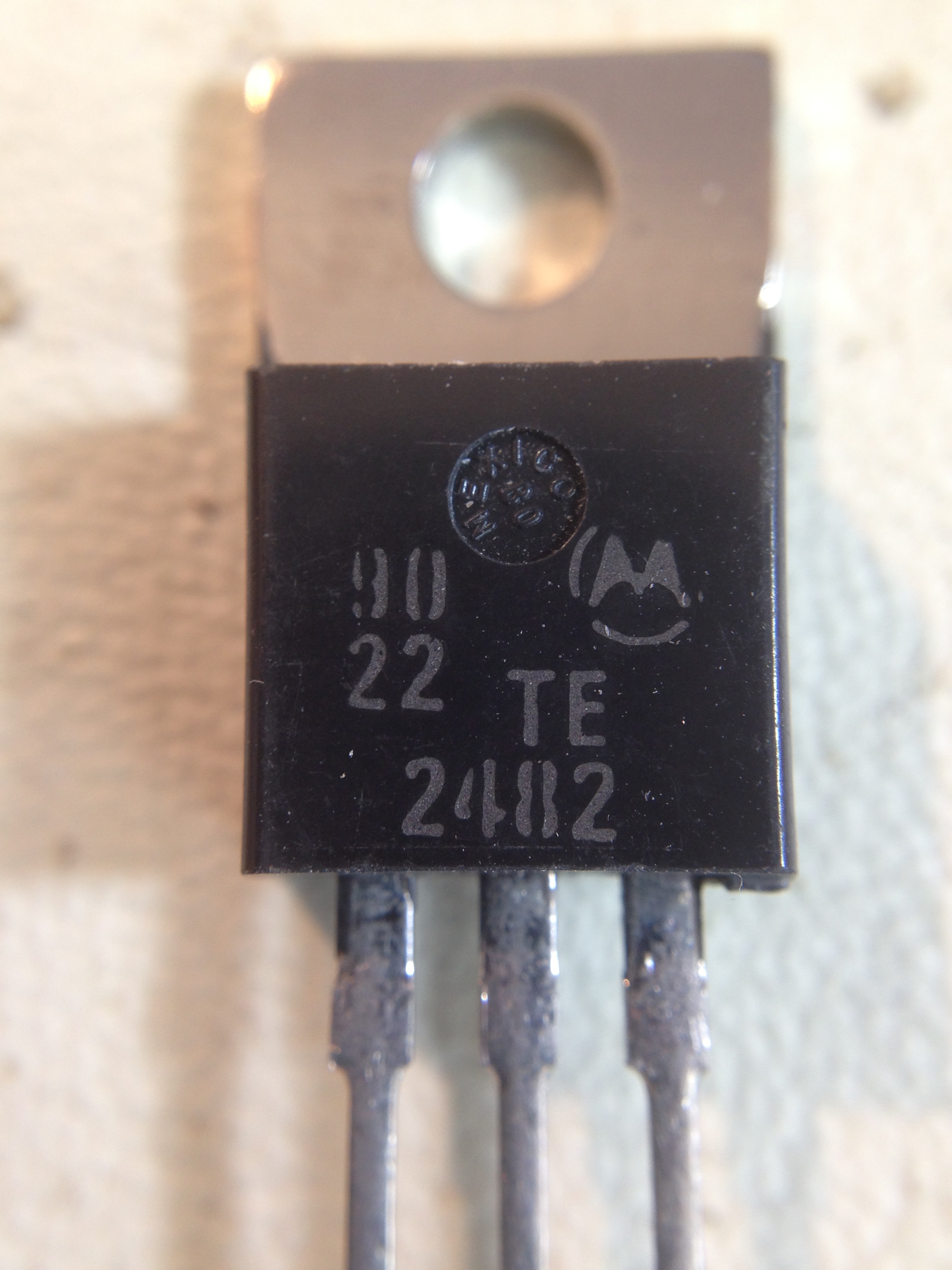
As for the transistor, pretty much any power NPN will do. I found this one in the junk pile, and I’m not even sure what it is. Googling turned up enough information to know it was an NPN transistor, but I never did find a data sheet for it.
Next up, I prototyped the circuit on the breadboard, both to make sure my transistor was correct, and to dial in the value of R2.
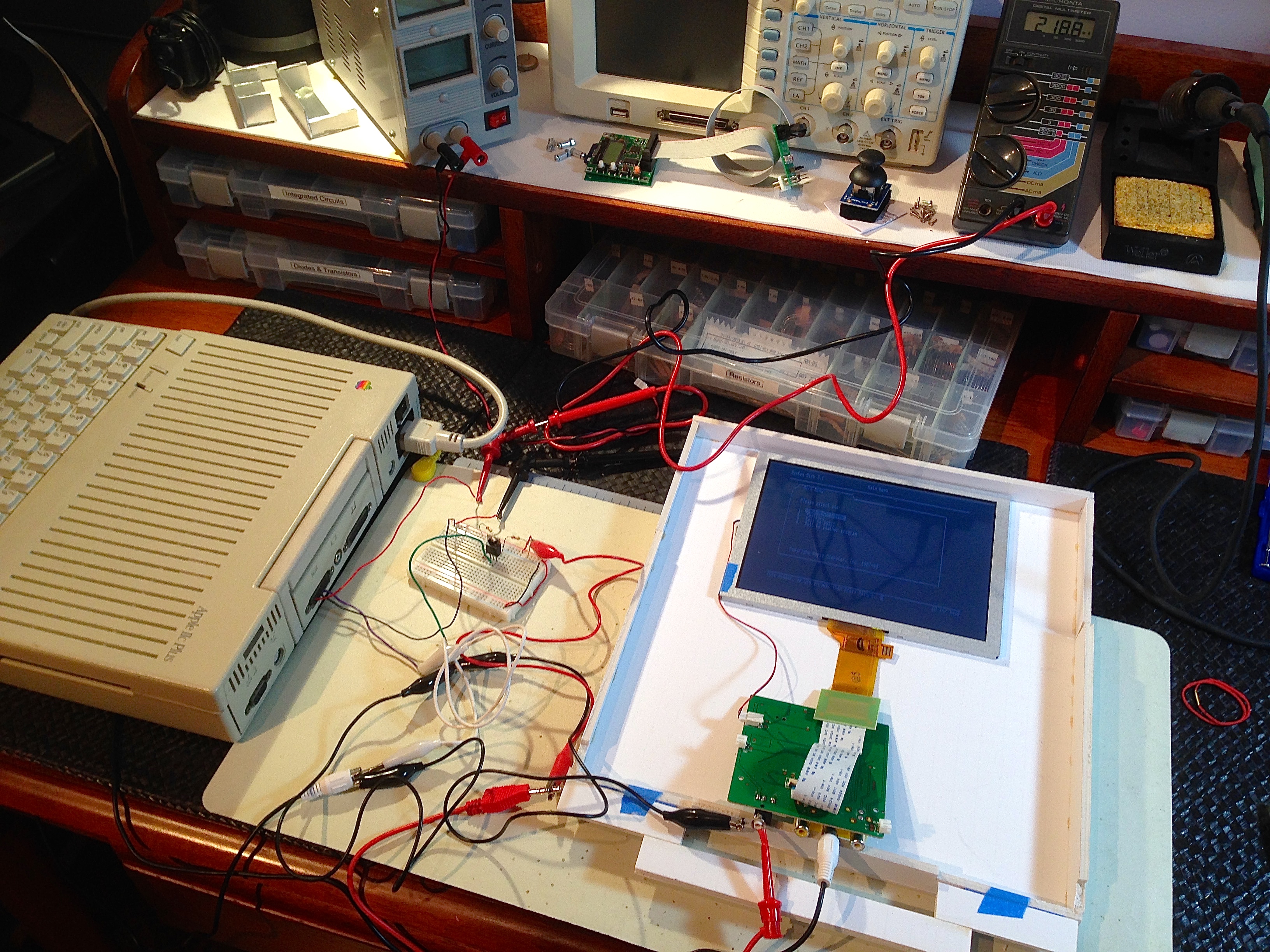
It works! Or does it? There’s a critical error in this mockup that I didn’t catch. It will come back to bite me in a major way later.
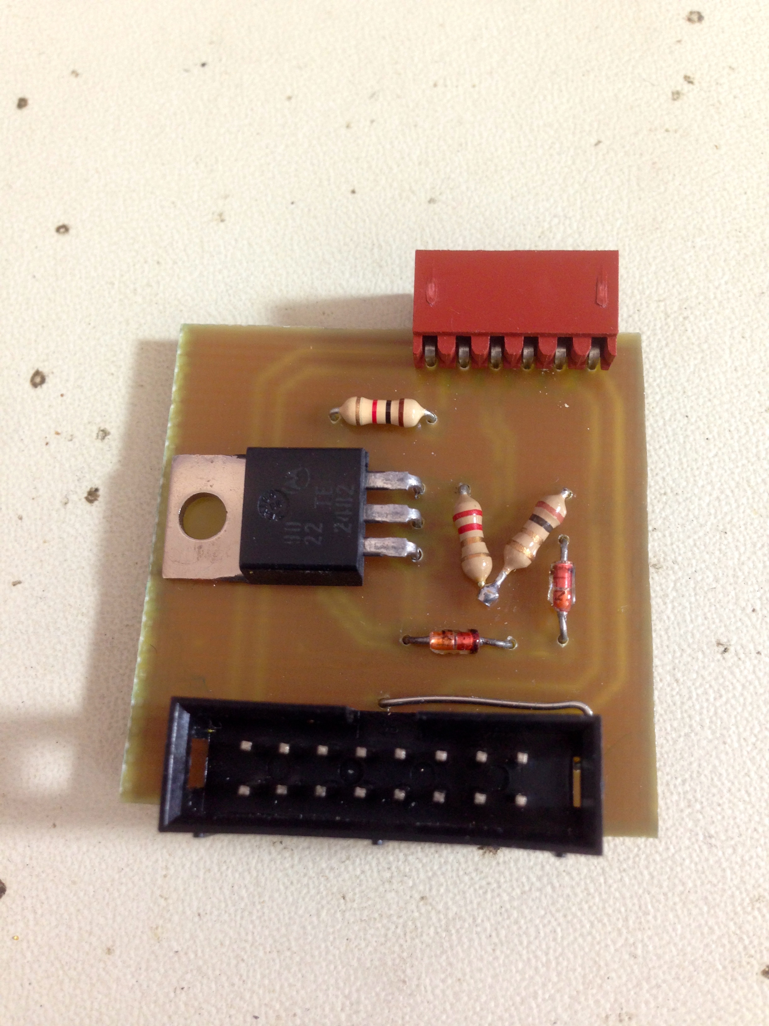
Ignorantly satisfied with this test, I proceeded to lay out a PCB. A circuit this simple would take only minutes to build on perfboard, but I like making PCBs, so I decided to do it. This is Fail #2.
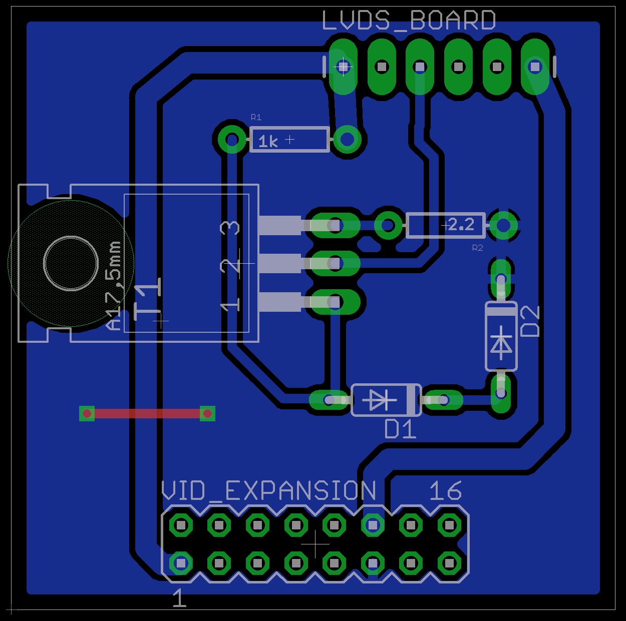
In my haste to lay out a nice board, I neglected to consider how the pins on the input header might map to the pins on the DB-15 port used by the IIc’s Expansion Port. In a moment of major absentmindedness, I simply mapped the header pins to the port pins as they happened to be numbered in the Eagle part. This was Fail #3.
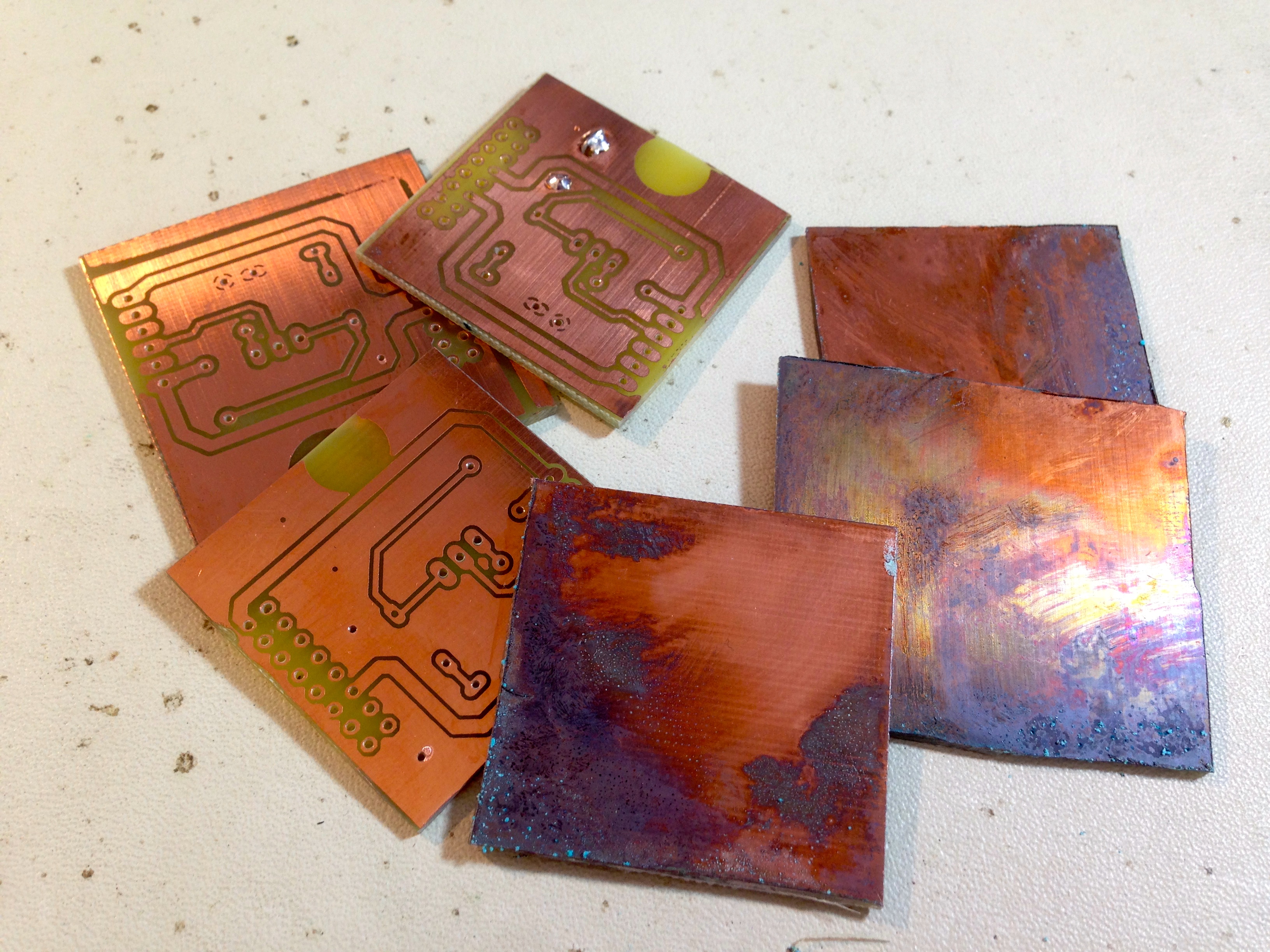
Next, I proceeded to etch this board using my usual method. Sometimes, being too comfortable with something is a source of error. Such was the case here. I’ve etched so many boards with this method and had so much success with it, that I got complacent about the kinds of errors that can creep into the process.
After exposing the board, it was ready for developing. However, the developer didn’t seem to be working. This batch of developer is many years old (this stuff lasts a long time), so I figured maybe it was finally time to replace it. I poured a fresh batch of developer into a bowl, and transferred to the board to it. The board instantly developed, then the traces were immediately obliterated. What was this? I’d never seen that happen before. Fail #4.
Trying to be scientific about it, I reasoned that the developer’s job is to remove the film which wasn’t cured in place by the UV exposure (which in turn protects the traces). If the traces are being wiped out, they must not have been cured properly. Perhaps I didn’t expose long enough. I used my usual exposure time, but these copper boards are old, and maybe they need more time. I exposed another board for 25% longer, and developed it again. It was instantly obliterated. Fail #5.
Undeterred, I increased the exposure time by 50%, re-exposed, and re-developed. The board was obliterated. Fail #6.
Thinking I was modifying the right variable, but in the wrong direction, I drastically reduced my exposure time. Re-expose, develop, and… obliterated. Fail #7.
Stumped by this, I decided it was time to RTFM. Re-reading the instructions on the developer (which I haven’t done since making this batch five years ago), I was reminded the developer is supposed to be diluted 10:1. I still have a bruise on my forehead from the magnitude of that facepalm. Fail #8.
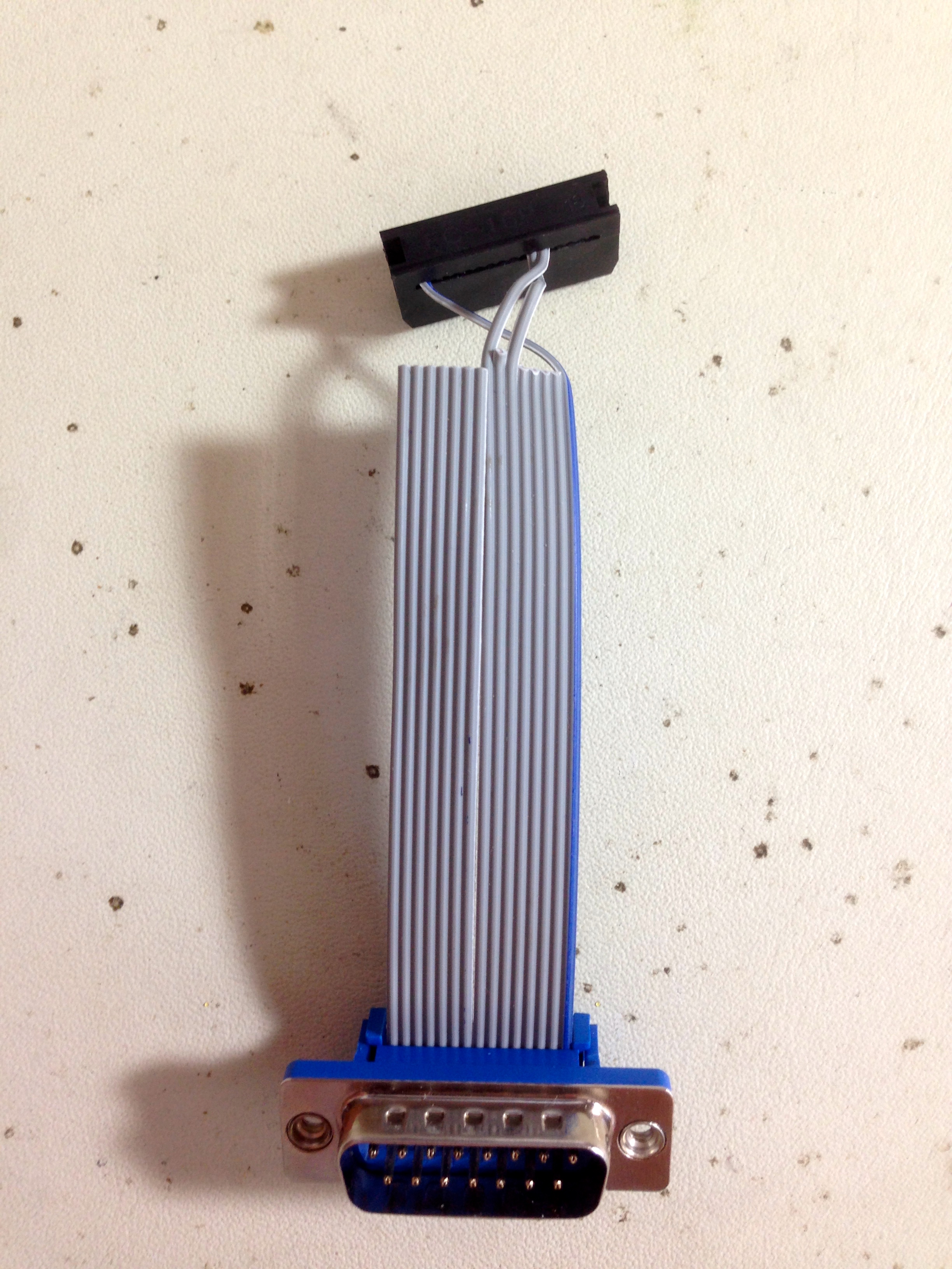
With that sorted out, I suddenly also realized my mistake earlier whereby I ordered the pins arbitrarily on the header. Determined to get that right, I busted out my notebook, and worked out the proper assignments. This was my first time using IDC ribbon connectors, and I wanted things to look nice.
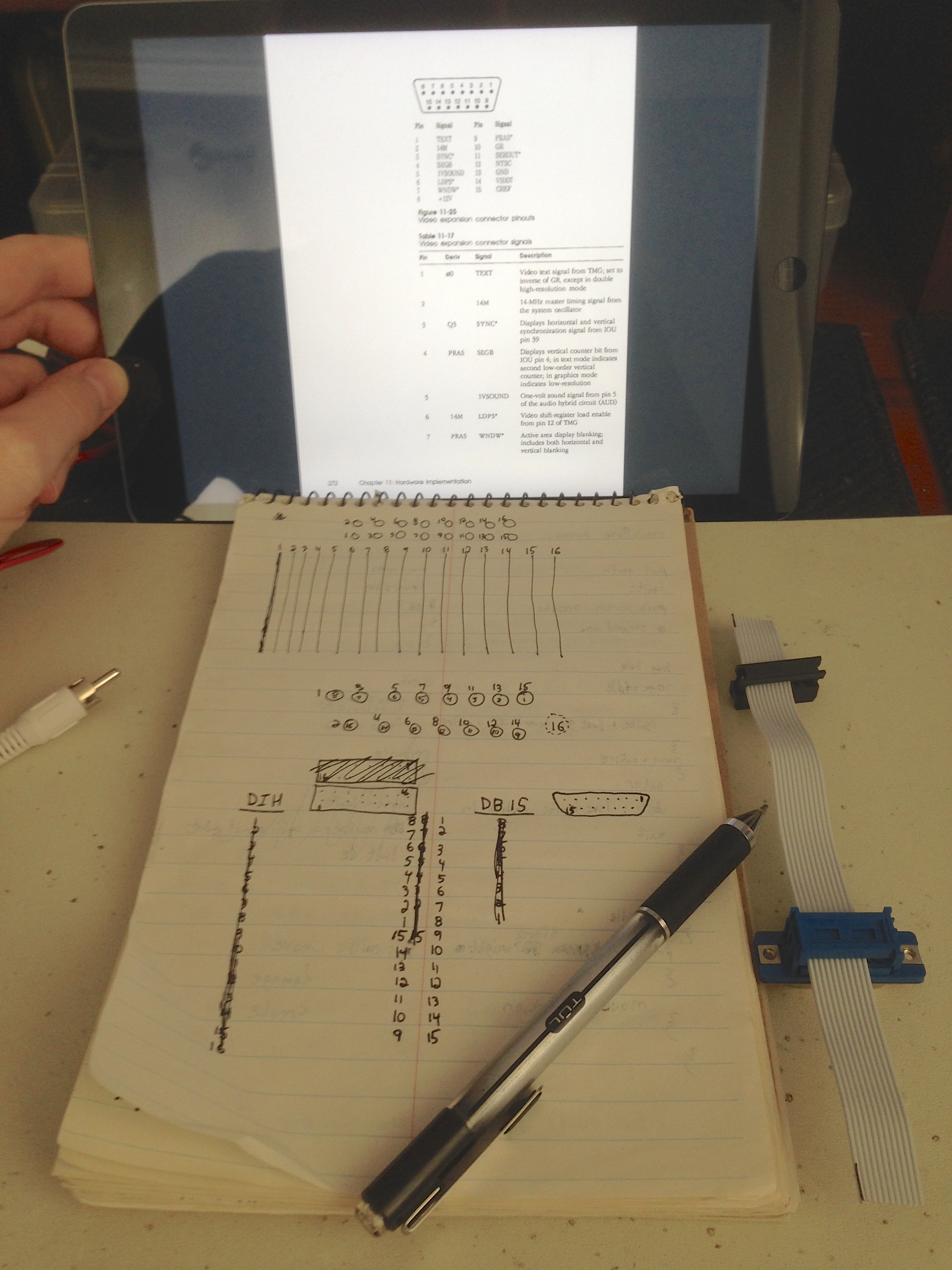
All the deduction you see above is correct… except it’s inverted. I neglected to account for the orientation of the PCB in the final enclosure, which means the plug is upside down from where I thought it would be. Fail #9.
Unknowingly, I felt chuffed about working all that out, and proceeded to etch the PCB with the new layout. I drilled the board, and began assembly, only to realize… I had inverted the exposure mask, so the PCB was a mirror image. Fail #10.
At this point it was personal. I was not going to get beaten by this damn board, even though I could have hand-made a dozen on perfboard by now. I very carefully checked and re-checked the mask to make sure it was correct, and etched another board. I had checked it so carefully, that I knew it was right, so I drilled it and began assembly. Only to find… it was inverted again. Fail #11.
The mind boggles at this, but I wasn’t going to give up. I regrouped, carefully aligned the board with how it was in Eagle, and exposed it again. Again confident that I had triple-checked the orientation, I drilled it and prepared to assemble the board. You guessed it, it was inverted. I wish I was making this up. Fail #12.
It finally hit me what the problem was. I haven’t used Eagle in a while, so I was a bit rusty with it. I forgot a quirk that has caused me some trouble in the past. When looking at the traces in Eagle’s board layout tool, you are looking down on them through the PCB, as though it were transparent. You are not looking at the copper from underneath. My brain always struggles with this, like some kind of PCB dyslexia. A Blondihacks reader once suggested always putting some text on the PCB so you can immediately see if it’s flipped or not. I disregarded this advice here, and it bit me. Three times.
Well, there was no way I was giving up now. After playing a Rocky training montage in my head, I was determined to come back and totally crush this board. I etched a final one in the correct orientation and proceeded to assemble it. Wouldn’t you know, this simple assembly fought me at every step. I got a bunch of solder whiskers that needed cleaning up. The pins on the header were oxidized and solder wouldn’t stick. I applied too much heat at one point and lifted a trace. I made every rookie mistake in the book on this. It was like the experienced board builder inside me was wiped out by a brain tumor or something. Don’t worry, eet’s nod a tooma.
With the PCB built, it was time to test it out. On my breadboard, I had determined experimentally that a 2.2Ω resistor worked well to calibrate the current limiter for 250mA. On the PCB, that limit shot up to 310mA. Fail #13.
The resistance on the PCB traces was different enough from the breadboard that the calibration was now off. Not having a tiny potentiometer that I could solder in for adjustment, I needed to find a value for a single resistor that I had on hand that would work. The trick is, it has to be installed fully in-circuit, or it won’t be an accurate test (as I learned with the breadboard). After several iterations of soldering and unsoldering a resistor into the R2 location, I determined that a value of 3.7Ω would work, which I could construct from two resistors in series that I happened to have. I hacked the two of them onto the board in the spot intended for one, and pressed on.

So far so good, right? We persevered through all the failures, and we’ve got something that will work. Time to hook it all up for real!
At this point, I did some probing to verify my signals were all correct before connecting the IIc Plus, and realized my mistake from earlier where I had inverted the IDC connector during my laying out of the wires. Fixing it meant either rebuilding the PCB yet again, or twisting my ribbon cable over. I really didn’t like either of those choices, because I was very sick of building this PCB, and for space reasons it was important that the ribbon lay flat. Since I’m only using three of the 15 signals, I opted to twist those and leave out the rest. I had intended to run all the IIc’s signals up to my board to allow easy future expansion, but I’ll fail that bridge when I come to it.
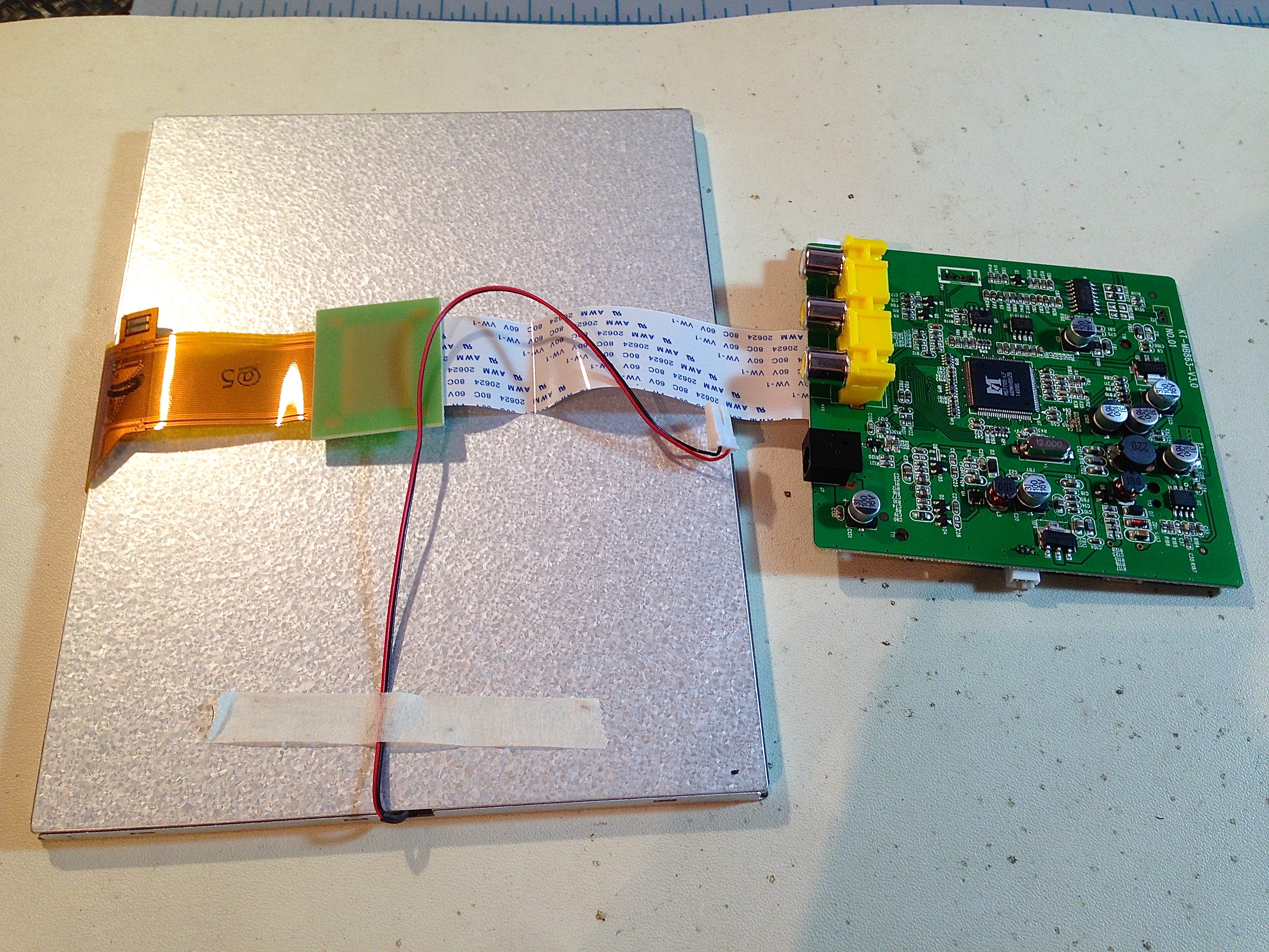
Next, I needed to connect the LCD driver board to my bridge board. The built-in DC power and RCA connectors were taking a lot of space, so I opted to strip them off and solder in my own connector instead.
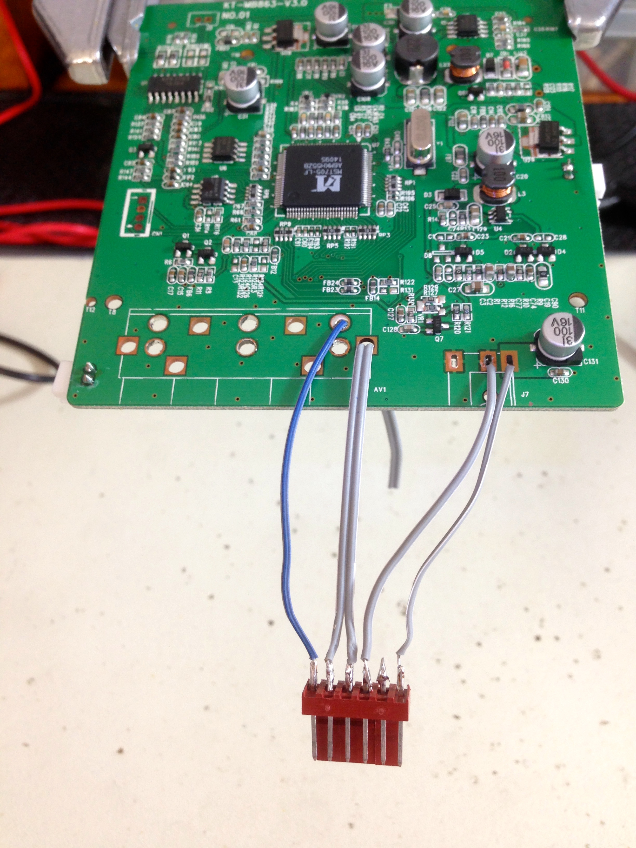
And…. nothing. The machine powers up and the backlight comes on, but the video won’t lock to the signal.
This makes no sense. The board matches the schematic, the schematic matches the breadboard, and the breadboard worked perfectly. Yet it was pretty clear what the problem was- the video signal wasn’t happy with its ground. The one weird thing about this board design is that the video signal is getting ground through the current-limited power supply. I wasn’t sure if this would work, but in my tests on the breadboard, it did. Yet, if I removed my limiter and patched the LCD directly into the IIc, everything worked. What was going on? I had dismantled my breadboard already, but luckily, I had photos of it (taken for this very blog, in fact). I zoomed in on the circuit, and the answer hit me like a slap in the face with a soggy catfish.
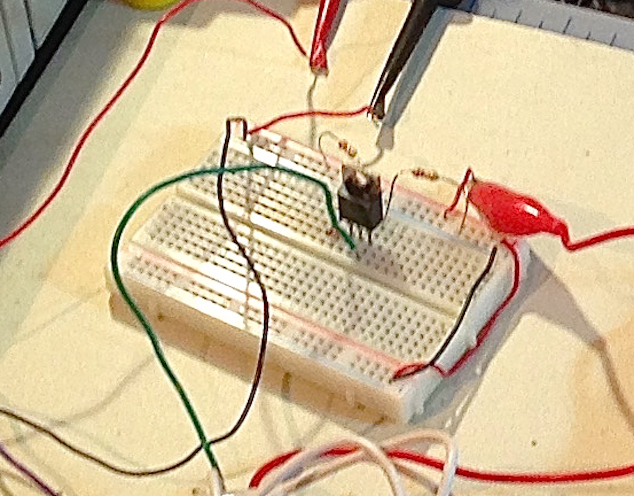
Do you see it? That green wire is the ground being provided to the LCD for power and video. Now look at the schematic from the top of the article. See it? If you know your TO-220 pinouts, you know that my ground in this photo is on the COLLECTOR, not the EMITTER as it should be. In this arrangement, I have in fact completely bypassed the current limiter without realizing it. This idea of running the video and power for the panel through a current limiter was an invalid one all along. Fail #14.
The video signal needs a direct ground from the IIc. I can’t run a dedicated ground wire for it, because the grounds are unified on the LCD driver board, which would create a short circuit across the back of my current limiter. At this point, I had no choice but to cut my losses. My whole idea was flawed from the start, and I had to travel a long horrible road to figure that out. In the end, since the panel only draws 200mA anyway (as verified by my multimeter), I opted to simply wire it into the IIc directly as I should have done in the first place.
If I’m worried about protection, I’ll put a 250mA fuse in there, like a normal person would have done from the very beginning. I was trying way too hard to be clever here, and it bit me in the ass. It bit me 14 times, in fact, and boy is my ass sore.
So, here’s a boot-up demo of the final display prototype. This entirely powered by the IIc. There’s nothing external connected here. The ribbon cable at the bottom runs down to the video expansion port on the back of the machine.
Here’s hoping the Teddy Top prototype goes a little smoother from here on. Now if you’ll excuse me, I need to go sit on something soft.
Are you booting from a physical floppy, ADTPro, or…?
In the video, I’m booting from a real floppy that was made with ADT Pro.
Wow, that’s a lot of biting. I know that feel, friend. 🙁
When the Teddy Top becomes a real thing, I will be so interested. I have an original //c that wants to be played with, but a) space is limited in small apartments and b) I think my color II monitor is dying. Your next project will be a combo RAM expansion/disk drive emulator, right?
…right?
If I have my way, it will have many cool features. 🙂
My frothing demand for this peripheral increases.
Oh, uh, are you planning for things to be compatible with the regular //c as well? Or is this a IIc Plus-only piece of kit?
I’m striving for regular IIc compatibility as well.
Cool! I actually like the regular IIc better. Not only because of the more-compatible 5.25″ drive, but the bigger connectors on the back are WAY less of a PITA to make cables for. My head hurts just from looking at a mini-DIN connector. Ugh.
The worst part for me was spotting your grounding error on the schematic and then reading all of your valiant efforts to make a PCB, and just waiting for the final realisation that the current-limiter was by-passed. But I’m really impressed with your determination. You’ve stuck with this through setback after setback — I wish I could keep my own motivation going in that kind of situation.
Anyway, I have a couple of suggestions: did you know that you can build the current-limiter using a PNP power transistor and therefore have it regulate the Vcc and keep a common Ground? Using PNP basically flips the polarity of the entire circuit.
Also, have you seen “polyfuses”? They’re a type self-resetting fuse that looks ideal for your application. They look like a square, yellow capacitor but act like a fuse, with the advantage they they reset themselves after “blowing”.
I sure could have used YOU a couple of days ago. 🙂 Seriously though, thanks for the tip on the PNP- I should have thought of that, honestly. Although, maybe it’s for the best. This current limiter is adding too much complexity anyway, so it’s kinda good that the effort failed and I was forced back to a more sensible plan.
I am familiar with Polyfuses, and you’re right- that sounds like a good way to go here. Thanks for all the good tips!
One day you’ll look back on this and laugh.
It’s already pretty funny. If we can’t laugh at ourselves, who can we laugh at? 🙂
Oh my! What a fight!
I really enjoy reading your blog, the language in your writing usually puts a smile on my face. But this time, I was laughing hard several times! When the board tuned out inverted for the 3rd time I was begging for mercy (on your behalf as well 😉 ). Please don’t get me wrong, you clearly went in with the best intentions! keep up the good work. I’m looking forward to see where this monster is going.
BTW, I saw you gave a speech on Veronica for HAD a little while ago. Was a nice surprise to see you on the speakers list!
Thanks! Never say die. 🙂
If you write a book, it’ll sell oodles. Your writing style is a joy to read, and it’s funny as intercourse. 😀
You could even go the lazy way most from-blog-to-book trajectories work: write 1/3rd of the content as book-only chapters, and the rest from the blog, maybe with some improvements and additional comments. I truly suspect you’d make le serious mucho moolah.
Too bad those boards are too small to make coasters out of. 😉 Maybe you could frame them all has a memorial?
Not if it’s a shot glass.
touché 🙂
This was highly entertaining. If I am entertained by your tribulations, does that count as schadenfreude? Or does it make a difference that you purposefully packaged it in an entertaining way? 😀
Did you by any chance happen to see my comment to your bootstrap article, mentioning how to get two levels of grey from the video circuitry? That is, instead of just ‘dark white’, you also get ‘bright black’. I think it would be cool if your project also just happened to allow for 16 colors instead of just 15.
I hope you don’t take anymore videos in vertical orientation, though. 😉
Thanks! It was intended to be schadenfreude for everyone. 🙂 It’s easy to laugh at it now, even if it wasn’t very amusing at the time. 🙂
I’ll look for that other comment.
I sort of apologize for the vertical video, but the fact is that it’s a perfect format for some kinds of things. The real problem is that YouTube refuses to make their player work with vertical video (despite smartphone cameras being ubiquitous for almost a decade now- come on Google!)
“You might be thinking, “why not use a simple fuse for that, then?”. Well, that would be entirely sensible,”
Not really! A fuse isn’t right for this situation. You can’t derate it enough.
You want a maximum current of 300 mA.
You have a working current of 200 mA.
It’s not in a climate-controlled environment, so you you have to imagine that temperatures as high as ~100-120 F are going to be common.
Time to blow depends on the fuse, but a 250 mA fuse probably would take at a minimum, at room temp, somewhere around a minute or so at 300 mA. Could be longer. I know of fuses that’d take days – odd to call that a 250 mA fuse, but fuses are intended to protect against *big* current surges, not little ones.
But the problem is how long would it take at *200* mA? Fuses still blow below their current limit – it just takes them longer. That same 250 mA fuse that takes around a minute at 300 mA would probably take about an *hour* at 200 mA. That’s all.
And when it gets hot, that fuse will blow faster. Sometimes lots faster. So definitely don’t add a fuse – that’ll just create another ‘fail’ point here.
Fuses usually need more than a factor of 2 derating above their ‘nominal’ current limit, and if anything would be damaged, their current limit should be around a factor of 2 below that ‘damage current’ (although really it’s probably a heat thing, so it’s more I^2 t that matters).
If you’re really worried (and it sounds like you’re not) you should just grab a load switch with a current limit (often grouped under ‘hot-swap controllers’, because that’s basically what they are), or just use a proper hot-swap controller in the first place.
If you’re being super-silly you could always try to build one with a logic level FET, sense resistor, an op-amp and a comparator, but that’s a little crazy – the chips aren’t that expensive, and could be sampled in small quantities.
That’s great info, Pat- thanks! I’m not an electrical engineer, as is no doubt painfully obvious. Information like this is always very helpful to myself and my readers.
In the end, I think it’s probably fine as-is. It has an 80-100mA margin on the spec for the port, and the spec is probably a bit conservative. The only thing I might be concerned about is a fault in the panel causing a dead short. That seems exceedingly unlikely, though.
Right, that’s what I’d worry about too, so a fuse isn’t crazy for protecting against that. But you wouldn’t want a 250 mA fuse: you’d want probably want a 500 mA fuse to be safe, and you’d actually have to hope that the rail isn’t current-limited in the first place, in which case the thing just sits there dissipating ~0.5W for a while until the fuse manages to blow.
I think I might worry about the opposite- would the fuse take too long to blow, and meanwhile whatever is driving that rail overloads and burns something out?
You make an interesting point about the rail possibly already being current-limited. I hadn’t considered that. I don’t have the schematic handy, but the wording in the technical reference manual suggests it isn’t. They warn strongly against exceeding 300mA, or the machine will be damaged. These machines were pretty primitive, so I would not be shocked* to learn there’s no protection on this source.
*Actually, maybe I would be shocked, if the current isn’t limited. 😛
Do polyfuses (resetable fuses) have different behaviour than regular fuses? The ones I’ve encountered on various things seem to “blow” pretty quickly. I don’t know much about them, but given they don’t work the same as a regular fuse, maybe their behaviour is different, and possible more suitable for what Quinn’s trying to accomplish.
Nah, same thing. Think of a polyfuse like a fuse embedded in plastic. Fuse heats up, polymer heats up, expands, and wire breaks. Fuse cools down, and polymer shrinks, and wire makes contact again. So you really get all the same problems.
Fuses and polyfuses are both fundamentally heat-based trips, which means that they are never going to have a really ‘sharp’ turnon. For that you need something that really senses current.
This reminds me a bit of the following joke were a higher power sends you signs and you just ignore them:
“Jacob is a very religious man. One day, a nearby river floods its banks and rushes into town, forcing Jacob to climb onto his garage roof. Soon, a man in a boat comes along and tells Jacob to get in.
Jacob says, “That’s very kind of you, but no thanks. God will take care of me.”
So, the boat leaves.
The water rises and Jacob has to climb onto the roof of his house. Another man in a boat comes along and tells Jacob to get in.
Jacob replies, “That’s very kind of you but no thanks. God will take care of me.”
The boat leaves.
The water rises further and soon Jacob is clinging to his chimney. Then a helicopter arrives and lowers a ladder. The helicopter pilot tells Jacob to climb up the ladder.
Jacob replies, “That’s very kind of you but no thanks. God will take care of me.”
The pilot says, “Are you really sure?”
Jacob says, “Yes, I’m sure that God will take care of me.”
Finally, the water rises too high and Jacob drowns. He goes up to Heaven and is met by God.
Jacob says to God, “You told me you would take care of me. What happened?”
God replies, “Well, I sent you two boats and a helicopter. What else did you want me to do?””
Great story, I love reading your articles!
Greetings from Holland
Sometimes just – stop – sleep over it – start again.
Always good advice. 🙂